Product Description
Product parameters and prices for reference only, the actual situation of the product please consult or call!
Accept customization ,And we offer OEM~
1. who are we?
We are based in ZheJiang , China, start from 2571,sell to North America(10.00%),South America(10.00%),Southeast
Asia(10.00%),Africa(10.00%),Mid East(10.00%),Eastern Asia(10.00%),Central America(10.00%),Northern Europe(10.00%),South
Asia(10.00%),Domestic Market(10.00%). There are total about 11-50 people in our office.
2. how can we guarantee quality?
Always a pre-production sample before mass production;
Always final Inspection before shipment;
3.what can you buy from us?
semi trailer axles, air suspensions , chamber,wheel ,slack adjuster and other related items.
4. why should you buy from us not from other suppliers?
We have a trailer parts production more than 10 years the supply chain
5. what services can we provide?
Accepted Delivery Terms: FOB,CIF,EXW;
Accepted Payment Currency:USD,EUR,JPY,CAD,AUD,HKD,GBP,CNY,CHF;
Accepted Payment Type: T/T;
Language Spoken:English,Chinese
6.what is the certificate
At present, the company can undertake CCS, ABS, BV, GL and other certification products /* January 22, 2571 19:08:37 */!function(){function s(e,r){var a,o={};try{e&&e.split(“,”).forEach(function(e,t){e&&(a=e.match(/(.*?):(.*)$/))&&1
| After-sales Service: | Availiable |
|---|---|
| Warranty: | Availiable |
| Condition: | New |
| Color: | Natural Color, Silver, Black |
| Certification: | CE, ISO |
| Material: | Stainless Steel |
| Customization: |
Available
| Customized Request |
|---|

Are cardan joints suitable for both high-torque and high-speed applications?
Cardan joints can be used in a variety of applications, but their suitability for high-torque and high-speed applications depends on several factors. Here’s a detailed explanation of the considerations regarding the use of cardan joints in such scenarios:
1. High-Torque Applications: Cardan joints are generally well-suited for high-torque applications. The design of the joint allows for the transmission of significant torque between misaligned shafts. However, it is important to consider the specific torque requirements and operating conditions. Factors such as the size and type of the joint, the material used, and the application’s torque demands should be taken into account. In extremely high-torque applications, alternative coupling mechanisms such as gear couplings or universal joints may be more appropriate.
2. High-Speed Applications: While cardan joints can operate at relatively high speeds, there are some limitations to consider. At high rotational speeds, cardan joints can experience increased vibration, imbalance, and potential for fatigue failure. The rotating components of the joint can generate centrifugal forces, which can impact the balance and stability of the system. To mitigate these issues, careful design considerations, including balancing and vibration analysis, may be necessary. In some cases, alternative coupling mechanisms like flexible couplings or constant velocity joints may be better suited for high-speed applications.
3. Balancing and Vibration Control: Balancing the rotating components, such as the driveshaft and the joint itself, is essential for minimizing vibration issues in high-torque and high-speed applications. Imbalance can lead to increased vibrations, reduced efficiency, and potential damage to the joint and other system components. Proper balancing techniques, including dynamic balancing during manufacturing or precision balancing during installation, can help achieve smoother operation and minimize vibration problems.
4. Material Selection: The material used in the construction of the cardan joint plays a crucial role in its suitability for high-torque and high-speed applications. High-strength materials, such as alloy steels, are often preferred for their ability to handle increased torque loads. Additionally, materials with good fatigue resistance and high-speed capabilities can help ensure the durability and reliability of the joint in demanding applications.
5. Application-Specific Factors: The suitability of cardan joints for high-torque and high-speed applications also depends on the specific requirements and operating conditions of the application. Factors such as load characteristics, duty cycles, temperature, and environmental conditions should be considered. It is important to consult with the manufacturer or engineering experts to determine the appropriate size, type, and configuration of the cardan joint for a particular high-torque or high-speed application.
In summary, cardan joints can be suitable for both high-torque and high-speed applications, but careful consideration of factors such as torque requirements, speed limitations, balancing, material selection, and application-specific conditions is necessary. Evaluating these factors and consulting with experts can help determine the optimal coupling solution for a given high-torque or high-speed application.

How do you retrofit an existing mechanical system with a cardan joint?
When retrofitting an existing mechanical system with a cardan joint, careful planning and consideration of various factors are necessary to ensure a successful integration. The retrofitting process involves modifying the system to accommodate the cardan joint’s requirements for torque transmission and misalignment compensation. Here’s a detailed explanation of how to retrofit an existing mechanical system with a cardan joint:
- Evaluate the Existing System: Begin by thoroughly evaluating the existing mechanical system to understand its design, components, and operational requirements. Identify the areas where a cardan joint can be integrated effectively and assess the feasibility of retrofitting.
- Identify the Integration Points: Determine the specific locations within the system where the cardan joint will be installed. This could include areas where torque transmission or misalignment compensation is required, such as connections between shafts, pulleys, or other rotating components.
- Measurements and Compatibility: Take accurate measurements of the existing components and spaces where the cardan joint will be installed. Ensure that the dimensions and specifications of the cardan joint are compatible with the available space and the system’s requirements. Consider factors such as shaft sizes, torque ratings, misalignment angles, and operating conditions.
- Design Modifications: Based on the evaluation and measurements, make necessary design modifications to accommodate the cardan joint. This may involve modifying shaft ends, adding or removing components, or adjusting mounting positions. Ensure that the modifications do not compromise the structural integrity or functionality of the system.
- Installation and Alignment: Install the cardan joint at the identified integration points according to the manufacturer’s guidelines and engineering best practices. Pay attention to proper alignment, ensuring that the joint aligns with the shafts and other connected components. Precise alignment is crucial for efficient torque transmission and to prevent excessive wear or failure.
- Secure Mounting: Properly secure the cardan joint to the system, ensuring that it is firmly and securely mounted. Use appropriate fasteners, couplings, or brackets to hold the joint in place and prevent any movement or vibration that could affect its performance.
- Lubrication and Maintenance: Follow the manufacturer’s recommendations for lubrication and maintenance of the cardan joint. Proper lubrication helps reduce friction, wear, and heat generation, ensuring smooth operation and longevity of the joint. Establish a maintenance schedule to regularly inspect and maintain the retrofit components to prevent any potential issues.
- Testing and Validation: After the retrofitting is complete, perform thorough testing to validate the functionality and performance of the retrofitted system. Test for torque transmission, misalignment compensation, and overall system operation. Monitor the system during operation to ensure that the cardan joint performs as expected and does not introduce any adverse effects.
It is essential to consult with experienced engineers or professionals specializing in retrofitting and cardan joint applications during the process. They can provide valuable guidance, expertise, and assistance in selecting the appropriate cardan joint, making design modifications, and ensuring a successful retrofit of the existing mechanical system.
How do you install a cardan joint?
Installing a cardan joint involves several steps to ensure proper alignment, secure attachment, and reliable operation. Here’s a detailed explanation of the process for installing a cardan joint:
- Prepare the Components: Gather all the necessary components for the installation, including the cardan joint, yokes, bearings, retaining rings, and any additional hardware required. Ensure that the components are clean and free from dirt, debris, or damage.
- Align the Shafts: Position the input and output shafts that will be connected by the cardan joint. Align the shafts as closely as possible to minimize misalignment. The shafts should be collinear and positioned at the desired angle or position for the specific application.
- Attach the Yokes: Attach the yokes to the input and output shafts. The yokes typically have holes or bores that match the diameter of the shafts. Securely fasten the yokes to the shafts using appropriate fasteners, such as set screws or bolts. Ensure that the yokes are tightly secured to prevent any movement or slippage during operation.
- Assemble the Cardan Joint: Assemble the cardan joint by connecting the yokes with the cross-shaped component. The cross should fit snugly into the yoke holes or bores. Apply a suitable lubricant to the bearings to ensure smooth rotation and reduce friction. Some cardan joints may have retaining rings or clips to secure the bearings in place. Make sure all the components are properly aligned and seated.
- Check for Clearance: Verify that there is adequate clearance between the cardan joint and any surrounding components, such as chassis or housing. Ensure that the cardan joint can rotate freely without any obstructions or interference. If necessary, adjust the positioning or mounting of the cardan joint to provide sufficient clearance.
- Perform a Trial Run: Before finalizing the installation, perform a trial run to check the functionality of the cardan joint. Rotate the connected shafts manually or with a suitable power source and observe the movement of the joint. Ensure that there are no unusual noises, binding, or excessive play. If any issues are detected, investigate and address them before proceeding.
- Secure the Cardan Joint: Once the functionality is confirmed, secure the cardan joint in its final position. This may involve tightening additional fasteners or locking mechanisms to keep the joint in place. Use the appropriate torque specifications provided by the manufacturer to ensure proper tightening without damaging the components.
- Perform Final Checks: Double-check all the connections, fasteners, and clearances to ensure that everything is properly installed and secured. Verify that the cardan joint operates smoothly and without any issues. Inspect the entire system for any signs of misalignment, excessive vibration, or other abnormalities.
It is important to follow the specific installation instructions provided by the manufacturer of the cardan joint, as different designs and configurations may have specific requirements. If you are unsure or unfamiliar with the installation process, it is recommended to consult the manufacturer’s documentation or seek assistance from a qualified professional to ensure a proper and safe installation of the cardan joint.


editor by CX 2024-05-09
China best U-Joint of Pto Shafts for Agricultural Tractors / Cardan Joint / Uj Cross / Universal Joint HS166
Product Description
Product parameters and prices for reference only, the actual situation of the product please consult or call!
Accept customization ,And we offer OEM~
1. who are we?
We are based in ZheJiang , China, start from 2571,sell to North America(10.00%),South America(10.00%),Southeast
Asia(10.00%),Africa(10.00%),Mid East(10.00%),Eastern Asia(10.00%),Central America(10.00%),Northern Europe(10.00%),South
Asia(10.00%),Domestic Market(10.00%). There are total about 11-50 people in our office.
2. how can we guarantee quality?
Always a pre-production sample before mass production;
Always final Inspection before shipment;
3.what can you buy from us?
semi trailer axles, air suspensions , chamber,wheel ,slack adjuster and other related items.
4. why should you buy from us not from other suppliers?
We have a trailer parts production more than 10 years the supply chain
5. what services can we provide?
Accepted Delivery Terms: FOB,CIF,EXW;
Accepted Payment Currency:USD,EUR,JPY,CAD,AUD,HKD,GBP,CNY,CHF;
Accepted Payment Type: T/T;
Language Spoken:English,Chinese
6.what is the certificate
At present, the company can undertake CCS, ABS, BV, GL and other certification products /* January 22, 2571 19:08:37 */!function(){function s(e,r){var a,o={};try{e&&e.split(“,”).forEach(function(e,t){e&&(a=e.match(/(.*?):(.*)$/))&&1
| After-sales Service: | Availiable |
|---|---|
| Warranty: | Availiable |
| Condition: | New |
| Color: | Natural Color, Silver, Black |
| Certification: | CE, ISO |
| Material: | Stainless Steel |
| Customization: |
Available
| Customized Request |
|---|

How do you ensure proper alignment when connecting a cardan joint?
Ensuring proper alignment when connecting a cardan joint is essential for its efficient and reliable operation. Proper alignment helps minimize stress, wear, and vibrations, ensuring optimal performance and longevity of the joint. Here’s a detailed explanation of how to ensure proper alignment when connecting a cardan joint:
- Initial Shaft Alignment: Start by aligning the input and output shafts as closely as possible before connecting the cardan joint. This initial alignment reduces the magnitude of misalignments that the joint needs to accommodate. It can be achieved by aligning the shaft axes parallel to each other in the desired orientation.
- Measure Misalignments: Use precision measurement tools, such as dial indicators or laser alignment systems, to measure the misalignments between the shaft axes. The three types of misalignments to consider are:
- Angular Misalignment (α): Measure the angular difference between the two shaft axes in the horizontal plane (X-Y plane).
- Parallel Misalignment (β): Measure the offset or displacement between the two shaft axes in the vertical plane (Z-axis).
- Axial Misalignment (γ): Measure the shift or displacement of one shaft along its axis with respect to the other shaft.
- Adjustment Techniques: Once the misalignments are measured, various adjustment techniques can be employed to achieve proper alignment:
- Shimming: Shimming involves placing thin metal shims between the joint and its mounting surfaces to adjust the alignment. Shims come in different thicknesses, allowing for precise alignment adjustments.
- Adjustable Mounting: Some cardan joints and their corresponding components may have adjustable mounting features. These features enable fine-tuning of the alignment by allowing for angular or axial adjustments.
- Flexible Couplings: In certain cases, flexible couplings with misalignment compensation capabilities can be used in conjunction with the cardan joint. These couplings absorb small misalignments, reducing the load on the cardan joint.
- Iterative Alignment: Achieving precise alignment may require an iterative process. Make adjustments, measure the misalignments again, and repeat the adjustment process until the desired alignment tolerances are met. It is important to follow the manufacturer’s guidelines and recommendations during this process.
- Verify Clearance and Rotation: After achieving the desired alignment, verify that there is adequate clearance between the joint and surrounding components to allow for proper rotation. Ensure that the joint can freely articulate without interference or binding.
- Secure Mounting: Once the alignment is verified, securely mount the cardan joint to its respective components. Use appropriate fasteners, such as bolts or retaining rings, and ensure they are tightened according to the manufacturer’s specifications.
Proper alignment is crucial for the efficient and reliable operation of the cardan joint. It helps minimize stress concentrations, premature wear, and excessive vibrations that can lead to joint failure. Additionally, it contributes to the overall performance and longevity of the connected machinery or system.
It is worth noting that alignment requirements may vary depending on the specific application, load conditions, and manufacturer recommendations. Consulting the cardan joint manufacturer’s guidelines and specifications is essential to ensure proper alignment and maximize the joint’s performance.

What are the key design considerations for optimizing cardan joint performance?
Optimizing the performance of a cardan joint requires careful design considerations that take into account various factors influencing its functionality, durability, and efficiency. By addressing these key design considerations, the performance of the cardan joint can be enhanced. Here’s a detailed explanation:
1. Mechanical Load and Torque Requirements: Understand the mechanical load and torque requirements of the application in which the cardan joint will be used. This includes analyzing the magnitude, direction, and variability of the loads and torques that the joint will experience. Properly selecting the cardan joint’s size, material, and configuration based on these requirements is crucial for optimizing its performance.
2. Operating Speed and Angular Misalignment: Consider the operating speed and the expected angular misalignment between the input and output shafts. The design of the cardan joint should accommodate the required speed range and angular movements while maintaining smooth operation and torque transmission. Balancing the joint’s ability to handle misalignments with its rotational capabilities is essential for optimizing performance.
3. Material Selection: Choose appropriate materials for the cardan joint components based on factors such as strength, durability, and resistance to wear and corrosion. Consider the specific operating conditions, including temperature, humidity, and exposure to chemicals or contaminants. Selecting high-quality materials that can withstand the application’s demands is crucial for optimizing performance and longevity.
4. Critical Dimensions and Clearances: Pay attention to critical dimensions and clearances within the cardan joint design. These include the size and geometry of the joint’s components, as well as the clearances between them. Properly dimensioning these aspects ensures sufficient strength, flexibility, and clearance for smooth operation and efficient torque transmission.
5. Lubrication and Sealing: Implement effective lubrication and sealing mechanisms to minimize friction, wear, and the ingress of contaminants. Proper lubrication ensures smooth operation and reduces power losses due to friction. Sealing the joint against dust, moisture, and other environmental factors helps maintain its performance and extend its lifespan.
6. Bearing and Bushing Design: Consider the design and selection of bearings or bushings used within the cardan joint. These components play a crucial role in supporting the joint’s rotational movement and transferring torque. Proper bearing or bushing selection, based on load capacity, lubrication requirements, and expected lifespan, is essential for optimizing the joint’s performance and reducing wear.
7. Structural Integrity and Rigidity: Ensure that the cardan joint assembly is structurally sound and rigid. Adequate stiffness and strength prevent excessive deflection and deformation during operation, leading to improved torque transmission efficiency and reduced wear on the joint and connected components.
8. Manufacturability and Quality Control: Consider manufacturability aspects during the design phase to ensure that the cardan joint can be produced consistently and cost-effectively. Implement quality control measures to verify dimensional accuracy, material quality, and functional performance of the manufactured joints, ensuring that they meet the required specifications and performance criteria.
9. Environmental Factors: Take into account environmental factors such as temperature variations, humidity, presence of corrosive agents, or exposure to vibrations. Design the cardan joint to withstand these conditions and incorporate appropriate protective measures or materials to ensure long-term performance and reliability.
10. Maintenance and Serviceability: Consider ease of maintenance and serviceability when designing the cardan joint. Provide access to lubrication points, inspection areas, and potential wear points for efficient maintenance activities. Designing for easy disassembly and replacement of worn components can minimize downtime and extend the joint’s lifespan.
By carefully addressing these key design considerations, the performance of a cardan joint can be optimized, resulting in improved torque transmission, durability, and overall efficiency. It is important to evaluate the specific requirements of the application and consult with experienced engineers or designers specializing in drivetrain systems to ensure the best design practices are followed.

Are there different types of cardan joints available?
Yes, there are different types of cardan joints available to suit various applications and requirements. The design and configuration of a cardan joint can vary based on factors such as load capacity, torque transmission, operating conditions, and installation constraints. Here’s a detailed explanation of some commonly used types of cardan joints:
- Single Universal Joint: The single universal joint is the most basic and commonly used type of cardan joint. It consists of two yokes connected by a cross, forming a single joint. This type of cardan joint allows for angular misalignment between the input and output shafts. It is often used in applications where misalignment angles are relatively small, and flexibility is required.
- Double Cardan Joint: The double cardan joint, also known as a constant velocity joint (CV joint), is an enhanced version of the single universal joint. It consists of two single universal joints connected by an intermediate shaft. This configuration helps to cancel out the velocity fluctuations and torque variations that can occur with a single joint. Double cardan joints are commonly used in applications where smooth and constant power transmission is required, such as in front-wheel drive vehicles.
- Tractor Joint: A tractor joint is a specialized type of cardan joint used in agricultural machinery, particularly in power take-off (PTO) systems. It consists of three yokes connected by two crosses. The tractor joint allows for higher torque transmission and can accommodate larger misalignment angles. It is designed to handle the demanding conditions and heavy loads often encountered in agricultural applications.
- Ball-and-Socket Joint: The ball-and-socket joint, also known as a Hooke’s joint, is another variant of the cardan joint. It consists of a cross with a spherical ball at each end, which fits into a corresponding socket in the yokes. The ball-and-socket joint provides greater flexibility and can accommodate larger angles of misalignment. It is commonly used in applications where significant angular movement is required, such as steering systems in vehicles.
- Flexible Coupling: While not strictly a cardan joint, flexible couplings serve a similar purpose in accommodating misalignment. Flexible couplings are often used in applications where the misalignment is minimal and torque transmission is a primary concern. They utilize elastomeric or flexible elements to provide flexibility and compensate for small misalignments between shafts.
These are some of the commonly used types of cardan joints. Each type offers specific advantages and is suitable for different applications based on factors such as misalignment requirements, torque transmission, and operating conditions. The selection of the appropriate cardan joint type depends on the specific needs of the application and the desired performance characteristics.
editor by CX 2024-04-03
China factory U-Joint of Pto Shafts for Agricultural Tractors / Cardan Joint / Uj Cross / Universal Joint HS166
Product Description
Product parameters and prices for reference only, the actual situation of the product please consult or call!
Accept customization ,And we offer OEM~
1. who are we?
We are based in ZheJiang , China, start from 2571,sell to North America(10.00%),South America(10.00%),Southeast
Asia(10.00%),Africa(10.00%),Mid East(10.00%),Eastern Asia(10.00%),Central America(10.00%),Northern Europe(10.00%),South
Asia(10.00%),Domestic Market(10.00%). There are total about 11-50 people in our office.
2. how can we guarantee quality?
Always a pre-production sample before mass production;
Always final Inspection before shipment;
3.what can you buy from us?
semi trailer axles, air suspensions , chamber,wheel ,slack adjuster and other related items.
4. why should you buy from us not from other suppliers?
We have a trailer parts production more than 10 years the supply chain
5. what services can we provide?
Accepted Delivery Terms: FOB,CIF,EXW;
Accepted Payment Currency:USD,EUR,JPY,CAD,AUD,HKD,GBP,CNY,CHF;
Accepted Payment Type: T/T;
Language Spoken:English,Chinese
6.what is the certificate
At present, the company can undertake CCS, ABS, BV, GL and other certification products /* January 22, 2571 19:08:37 */!function(){function s(e,r){var a,o={};try{e&&e.split(“,”).forEach(function(e,t){e&&(a=e.match(/(.*?):(.*)$/))&&1
| After-sales Service: | Availiable |
|---|---|
| Warranty: | Availiable |
| Condition: | New |
| Color: | Natural Color, Silver, Black |
| Certification: | CE, ISO |
| Material: | Stainless Steel |
| Customization: |
Available
| Customized Request |
|---|
How do you ensure proper alignment when connecting a cardan joint?
Ensuring proper alignment when connecting a cardan joint is essential for its efficient and reliable operation. Proper alignment helps minimize stress, wear, and vibrations, ensuring optimal performance and longevity of the joint. Here’s a detailed explanation of how to ensure proper alignment when connecting a cardan joint:
- Initial Shaft Alignment: Start by aligning the input and output shafts as closely as possible before connecting the cardan joint. This initial alignment reduces the magnitude of misalignments that the joint needs to accommodate. It can be achieved by aligning the shaft axes parallel to each other in the desired orientation.
- Measure Misalignments: Use precision measurement tools, such as dial indicators or laser alignment systems, to measure the misalignments between the shaft axes. The three types of misalignments to consider are:
- Angular Misalignment (α): Measure the angular difference between the two shaft axes in the horizontal plane (X-Y plane).
- Parallel Misalignment (β): Measure the offset or displacement between the two shaft axes in the vertical plane (Z-axis).
- Axial Misalignment (γ): Measure the shift or displacement of one shaft along its axis with respect to the other shaft.
- Adjustment Techniques: Once the misalignments are measured, various adjustment techniques can be employed to achieve proper alignment:
- Shimming: Shimming involves placing thin metal shims between the joint and its mounting surfaces to adjust the alignment. Shims come in different thicknesses, allowing for precise alignment adjustments.
- Adjustable Mounting: Some cardan joints and their corresponding components may have adjustable mounting features. These features enable fine-tuning of the alignment by allowing for angular or axial adjustments.
- Flexible Couplings: In certain cases, flexible couplings with misalignment compensation capabilities can be used in conjunction with the cardan joint. These couplings absorb small misalignments, reducing the load on the cardan joint.
- Iterative Alignment: Achieving precise alignment may require an iterative process. Make adjustments, measure the misalignments again, and repeat the adjustment process until the desired alignment tolerances are met. It is important to follow the manufacturer’s guidelines and recommendations during this process.
- Verify Clearance and Rotation: After achieving the desired alignment, verify that there is adequate clearance between the joint and surrounding components to allow for proper rotation. Ensure that the joint can freely articulate without interference or binding.
- Secure Mounting: Once the alignment is verified, securely mount the cardan joint to its respective components. Use appropriate fasteners, such as bolts or retaining rings, and ensure they are tightened according to the manufacturer’s specifications.
Proper alignment is crucial for the efficient and reliable operation of the cardan joint. It helps minimize stress concentrations, premature wear, and excessive vibrations that can lead to joint failure. Additionally, it contributes to the overall performance and longevity of the connected machinery or system.
It is worth noting that alignment requirements may vary depending on the specific application, load conditions, and manufacturer recommendations. Consulting the cardan joint manufacturer’s guidelines and specifications is essential to ensure proper alignment and maximize the joint’s performance.
What are the key design considerations for optimizing cardan joint performance?
Optimizing the performance of a cardan joint requires careful design considerations that take into account various factors influencing its functionality, durability, and efficiency. By addressing these key design considerations, the performance of the cardan joint can be enhanced. Here’s a detailed explanation:
1. Mechanical Load and Torque Requirements: Understand the mechanical load and torque requirements of the application in which the cardan joint will be used. This includes analyzing the magnitude, direction, and variability of the loads and torques that the joint will experience. Properly selecting the cardan joint’s size, material, and configuration based on these requirements is crucial for optimizing its performance.
2. Operating Speed and Angular Misalignment: Consider the operating speed and the expected angular misalignment between the input and output shafts. The design of the cardan joint should accommodate the required speed range and angular movements while maintaining smooth operation and torque transmission. Balancing the joint’s ability to handle misalignments with its rotational capabilities is essential for optimizing performance.
3. Material Selection: Choose appropriate materials for the cardan joint components based on factors such as strength, durability, and resistance to wear and corrosion. Consider the specific operating conditions, including temperature, humidity, and exposure to chemicals or contaminants. Selecting high-quality materials that can withstand the application’s demands is crucial for optimizing performance and longevity.
4. Critical Dimensions and Clearances: Pay attention to critical dimensions and clearances within the cardan joint design. These include the size and geometry of the joint’s components, as well as the clearances between them. Properly dimensioning these aspects ensures sufficient strength, flexibility, and clearance for smooth operation and efficient torque transmission.
5. Lubrication and Sealing: Implement effective lubrication and sealing mechanisms to minimize friction, wear, and the ingress of contaminants. Proper lubrication ensures smooth operation and reduces power losses due to friction. Sealing the joint against dust, moisture, and other environmental factors helps maintain its performance and extend its lifespan.
6. Bearing and Bushing Design: Consider the design and selection of bearings or bushings used within the cardan joint. These components play a crucial role in supporting the joint’s rotational movement and transferring torque. Proper bearing or bushing selection, based on load capacity, lubrication requirements, and expected lifespan, is essential for optimizing the joint’s performance and reducing wear.
7. Structural Integrity and Rigidity: Ensure that the cardan joint assembly is structurally sound and rigid. Adequate stiffness and strength prevent excessive deflection and deformation during operation, leading to improved torque transmission efficiency and reduced wear on the joint and connected components.
8. Manufacturability and Quality Control: Consider manufacturability aspects during the design phase to ensure that the cardan joint can be produced consistently and cost-effectively. Implement quality control measures to verify dimensional accuracy, material quality, and functional performance of the manufactured joints, ensuring that they meet the required specifications and performance criteria.
9. Environmental Factors: Take into account environmental factors such as temperature variations, humidity, presence of corrosive agents, or exposure to vibrations. Design the cardan joint to withstand these conditions and incorporate appropriate protective measures or materials to ensure long-term performance and reliability.
10. Maintenance and Serviceability: Consider ease of maintenance and serviceability when designing the cardan joint. Provide access to lubrication points, inspection areas, and potential wear points for efficient maintenance activities. Designing for easy disassembly and replacement of worn components can minimize downtime and extend the joint’s lifespan.
By carefully addressing these key design considerations, the performance of a cardan joint can be optimized, resulting in improved torque transmission, durability, and overall efficiency. It is important to evaluate the specific requirements of the application and consult with experienced engineers or designers specializing in drivetrain systems to ensure the best design practices are followed.

Can you explain the purpose of a cardan joint in a drive shaft?
A cardan joint, also known as a universal joint or U-joint, serves a crucial purpose in a drive shaft. The drive shaft is responsible for transmitting rotational motion and torque from the engine or power source to the wheels or driven components. Here’s a detailed explanation of the purpose of a cardan joint in a drive shaft:
A drive shaft is a mechanical component that connects the output of the engine or power source to the wheels or driven components of a vehicle or machinery. It is typically a tubular shaft that rotates at high speeds and transmits the torque generated by the engine to propel the vehicle or operate the machinery. The drive shaft needs to accommodate various factors, including changes in distance, misalignment, and different angles between the engine and the wheels or driven components.
This is where the cardan joint comes into play. The cardan joint is located at each end of the drive shaft, connecting it to the engine or power source and the wheels or driven components. The purpose of the cardan joint is to allow the drive shaft to transmit rotational motion and torque while accommodating the misalignment and changes in angles that occur between these components.
When the engine or power source rotates, it generates rotational motion and torque. The cardan joint at the engine end of the drive shaft receives this rotational motion and torque and transfers it to the drive shaft. As the drive shaft rotates, the cardan joint allows for the changes in angle and misalignment between the engine and the wheels or driven components. This flexibility of the cardan joint ensures that the drive shaft can operate smoothly and transmit power effectively, even when the components are not perfectly aligned or when there are variations in the angles.
At the other end of the drive shaft, another cardan joint is present to connect the drive shaft to the wheels or driven components. This cardan joint receives the rotational motion and torque from the drive shaft and transfers it to the wheels or driven components, allowing them to rotate and perform their intended functions.
The cardan joint in the drive shaft effectively compensates for misalignment, changes in angles, and variations in distance between the engine and the wheels or driven components. It ensures that the rotational motion and torque generated by the engine can be transmitted smoothly and efficiently to propel the vehicle or operate the machinery.
Overall, the purpose of the cardan joint in a drive shaft is to provide flexibility and accommodate misalignment, allowing for the effective transmission of rotational motion and torque between the engine or power source and the wheels or driven components.
editor by CX 2024-03-05
China Professional U-Joint of Pto Shafts for Agricultural Tractors / Cardan Joint / Uj Cross / Universal Joint HS166
Product Description
Product parameters and prices for reference only, the actual situation of the product please consult or call!
Accept customization ,And we offer OEM~
1. who are we?
We are based in ZheJiang , China, start from 2571,sell to North America(10.00%),South America(10.00%),Southeast
Asia(10.00%),Africa(10.00%),Mid East(10.00%),Eastern Asia(10.00%),Central America(10.00%),Northern Europe(10.00%),South
Asia(10.00%),Domestic Market(10.00%). There are total about 11-50 people in our office.
2. how can we guarantee quality?
Always a pre-production sample before mass production;
Always final Inspection before shipment;
3.what can you buy from us?
semi trailer axles, air suspensions , chamber,wheel ,slack adjuster and other related items.
4. why should you buy from us not from other suppliers?
We have a trailer parts production more than 10 years the supply chain
5. what services can we provide?
Accepted Delivery Terms: FOB,CIF,EXW;
Accepted Payment Currency:USD,EUR,JPY,CAD,AUD,HKD,GBP,CNY,CHF;
Accepted Payment Type: T/T;
Language Spoken:English,Chinese
6.what is the certificate
At present, the company can undertake CCS, ABS, BV, GL and other certification products
| After-sales Service: | Availiable |
|---|---|
| Warranty: | Availiable |
| Condition: | New |
| Color: | Natural Color, Silver, Black |
| Certification: | CE, ISO |
| Material: | Stainless Steel |
| Customization: |
Available
| Customized Request |
|---|

What are the potential challenges in designing and manufacturing cardan joints?
Designing and manufacturing cardan joints can present several challenges that need to be carefully addressed to ensure the functionality, durability, and performance of the joint. Here’s a detailed explanation of the potential challenges in designing and manufacturing cardan joints:
- Misalignment Compensation: One of the primary challenges is designing the joint to effectively compensate for misalignments between the input and output shafts. The joint must accommodate angular, parallel, and axial misalignments while maintaining smooth torque transmission and minimizing stress concentrations.
- Load Capacity and Torque Transmission: Cardan joints are often used in applications that require the transmission of high torque and handling substantial loads. Designing the joint to withstand these loads while ensuring efficient torque transmission can be a challenge. It involves selecting appropriate materials, optimizing the joint’s geometry, and considering factors like bearing capacity and fatigue resistance.
- Bearing Arrangement: Proper bearing arrangement is crucial for the smooth operation and longevity of the cardan joint. Ensuring adequate support and load distribution on the bearings can be challenging, especially in applications with high speeds, heavy loads, or extreme operating conditions. The design must consider factors such as bearing type, size, lubrication, and alignment to optimize performance.
- Compact Design: Cardan joints are often used in systems with limited space, requiring a compact design. Designing a compact joint while maintaining its mechanical properties, load capacity, and misalignment compensation capabilities can be challenging. It involves optimizing the joint’s dimensions, yoke or flange design, and component arrangement to fit within the given space constraints.
- Torsional Rigidity and Vibration: Cardan joints introduce some level of torsional compliance due to their flexible nature. Excessive torsional compliance can lead to vibrations, power loss, and reduced system performance. Designing the joint to provide adequate torsional rigidity while still accommodating misalignments is a challenge that requires careful consideration of the joint’s materials, cross-sectional geometry, and manufacturing processes.
- Manufacturability and Precision: Manufacturing cardan joints with the required precision and quality can be challenging. The joint’s components, such as yokes, cross members, and bearings, need to be manufactured to close tolerances and assembled accurately. Specialized manufacturing techniques, such as forging, machining, and heat treatment, may be required to achieve the desired mechanical properties and dimensional accuracy.
- Material Selection: Selecting the appropriate materials for cardan joints is critical for their performance and durability. The materials must possess high strength, fatigue resistance, and wear resistance to withstand the operating conditions and loads. Balancing material properties, cost considerations, and manufacturability can be challenging during the design process.
- Quality Control and Testing: Ensuring the quality and reliability of cardan joints requires comprehensive testing and quality control measures. Conducting tests to evaluate factors such as torque capacity, misalignment compensation, fatigue life, and dimensional accuracy can be challenging. Implementing effective quality control procedures throughout the manufacturing process is essential to identify and rectify any potential issues.
Addressing these challenges requires a multidisciplinary approach, involving engineering expertise in areas such as mechanical design, materials science, manufacturing processes, and quality assurance. Collaboration between design engineers, manufacturing engineers, and quality control personnel is crucial to overcome these challenges and produce high-quality cardan joints.
It is important to note that the specific challenges may vary depending on the application requirements, industry standards, and operating conditions. Continuous research, development, and advancements in design and manufacturing techniques contribute to overcoming these challenges and improving the performance and reliability of cardan joints.
How do you ensure reliable and consistent performance in a cardan joint?
Ensuring reliable and consistent performance in a cardan joint requires attention to various factors, including proper design, maintenance, and operating practices. By following best practices and considering key considerations, the reliability and performance of a cardan joint can be optimized. Here’s a detailed explanation:
1. Proper Design and Selection: The first step is to ensure the cardan joint is properly designed and selected for the intended application. Consider factors such as load requirements, operating conditions (including speed and temperature), misalignment angles, and torque transmission needs. Choose a cardan joint that is appropriately sized and rated to handle the specific demands of the application.
2. Material Selection: Selecting the appropriate materials for the cardan joint is crucial for long-term performance. Consider factors such as strength, fatigue resistance, and corrosion resistance. The materials should be compatible with the operating environment and any potential exposure to chemicals, moisture, or extreme temperatures.
3. Regular Inspection and Maintenance: Implement a regular inspection and maintenance schedule to identify any signs of wear, damage, or misalignment. This includes checking for excessive play, backlash, or abnormal vibrations. Regularly lubricate the joint as per the manufacturer’s recommendations and ensure that seals are intact to prevent contamination.
4. Alignment and Installation: Proper alignment during installation is critical for optimal performance. Ensure that the joint is aligned correctly with the connected shafts to minimize misalignment and reduce stress on the joint. Precise alignment helps to minimize wear, maximize torque transmission efficiency, and extend the life of the joint.
5. Load Considerations: Be mindful of the loads applied to the cardan joint. Avoid exceeding the recommended load limits and consider factors such as shock loads, torsional forces, and variations in load during operation. Excessive loads can lead to premature wear, fatigue, and failure of the joint.
6. Temperature Management: Maintain suitable operating temperatures for the cardan joint. Excessive heat or extreme temperature fluctuations can affect the performance and longevity of the joint. Ensure proper cooling or lubrication mechanisms are in place if operating conditions generate significant heat.
7. Training and Operator Awareness: Provide proper training to operators and maintenance personnel regarding the cardan joint’s operation, maintenance requirements, and potential failure modes. Encourage regular inspection and reporting of any abnormalities to address issues promptly.
8. Consider Additional Measures: Depending on the application and specific requirements, additional measures can be implemented to enhance performance and reliability. This may include incorporating backlash compensation systems, using precision-aligned cardan joints, or integrating monitoring systems to detect early signs of wear or misalignment.
By considering these factors and implementing best practices, reliable and consistent performance can be achieved in a cardan joint. Regular monitoring, maintenance, and prompt corrective actions are essential to ensure the joint operates optimally and delivers the expected performance throughout its service life.
Are there different types of cardan joints available?
Yes, there are different types of cardan joints available to suit various applications and requirements. The design and configuration of a cardan joint can vary based on factors such as load capacity, torque transmission, operating conditions, and installation constraints. Here’s a detailed explanation of some commonly used types of cardan joints:
- Single Universal Joint: The single universal joint is the most basic and commonly used type of cardan joint. It consists of two yokes connected by a cross, forming a single joint. This type of cardan joint allows for angular misalignment between the input and output shafts. It is often used in applications where misalignment angles are relatively small, and flexibility is required.
- Double Cardan Joint: The double cardan joint, also known as a constant velocity joint (CV joint), is an enhanced version of the single universal joint. It consists of two single universal joints connected by an intermediate shaft. This configuration helps to cancel out the velocity fluctuations and torque variations that can occur with a single joint. Double cardan joints are commonly used in applications where smooth and constant power transmission is required, such as in front-wheel drive vehicles.
- Tractor Joint: A tractor joint is a specialized type of cardan joint used in agricultural machinery, particularly in power take-off (PTO) systems. It consists of three yokes connected by two crosses. The tractor joint allows for higher torque transmission and can accommodate larger misalignment angles. It is designed to handle the demanding conditions and heavy loads often encountered in agricultural applications.
- Ball-and-Socket Joint: The ball-and-socket joint, also known as a Hooke’s joint, is another variant of the cardan joint. It consists of a cross with a spherical ball at each end, which fits into a corresponding socket in the yokes. The ball-and-socket joint provides greater flexibility and can accommodate larger angles of misalignment. It is commonly used in applications where significant angular movement is required, such as steering systems in vehicles.
- Flexible Coupling: While not strictly a cardan joint, flexible couplings serve a similar purpose in accommodating misalignment. Flexible couplings are often used in applications where the misalignment is minimal and torque transmission is a primary concern. They utilize elastomeric or flexible elements to provide flexibility and compensate for small misalignments between shafts.
These are some of the commonly used types of cardan joints. Each type offers specific advantages and is suitable for different applications based on factors such as misalignment requirements, torque transmission, and operating conditions. The selection of the appropriate cardan joint type depends on the specific needs of the application and the desired performance characteristics.
editor by CX 2023-12-12
China supplier U-Joint of Pto Shafts for Agricultural Tractors / Cardan Joint / Uj Cross / Universal Joint HS166
Product Description
Product parameters and prices for reference only, the actual situation of the product please consult or call!
Accept customization ,And we offer OEM~
1. who are we?
We are based in ZheJiang , China, start from 2571,sell to North America(10.00%),South America(10.00%),Southeast
Asia(10.00%),Africa(10.00%),Mid East(10.00%),Eastern Asia(10.00%),Central America(10.00%),Northern Europe(10.00%),South
Asia(10.00%),Domestic Market(10.00%). There are total about 11-50 people in our office.
2. how can we guarantee quality?
Always a pre-production sample before mass production;
Always final Inspection before shipment;
3.what can you buy from us?
semi trailer axles, air suspensions , chamber,wheel ,slack adjuster and other related items.
4. why should you buy from us not from other suppliers?
We have a trailer parts production more than 10 years the supply chain
5. what services can we provide?
Accepted Delivery Terms: FOB,CIF,EXW;
Accepted Payment Currency:USD,EUR,JPY,CAD,AUD,HKD,GBP,CNY,CHF;
Accepted Payment Type: T/T;
Language Spoken:English,Chinese
6.what is the certificate
At present, the company can undertake CCS, ABS, BV, GL and other certification products
| After-sales Service: | Availiable |
|---|---|
| Warranty: | Availiable |
| Condition: | New |
| Color: | Natural Color, Silver, Black |
| Certification: | CE, ISO |
| Material: | Stainless Steel |
| Customization: |
Available
| Customized Request |
|---|
How do you ensure proper alignment when connecting a cardan joint?
Ensuring proper alignment when connecting a cardan joint is essential for its efficient and reliable operation. Proper alignment helps minimize stress, wear, and vibrations, ensuring optimal performance and longevity of the joint. Here’s a detailed explanation of how to ensure proper alignment when connecting a cardan joint:
- Initial Shaft Alignment: Start by aligning the input and output shafts as closely as possible before connecting the cardan joint. This initial alignment reduces the magnitude of misalignments that the joint needs to accommodate. It can be achieved by aligning the shaft axes parallel to each other in the desired orientation.
- Measure Misalignments: Use precision measurement tools, such as dial indicators or laser alignment systems, to measure the misalignments between the shaft axes. The three types of misalignments to consider are:
- Angular Misalignment (α): Measure the angular difference between the two shaft axes in the horizontal plane (X-Y plane).
- Parallel Misalignment (β): Measure the offset or displacement between the two shaft axes in the vertical plane (Z-axis).
- Axial Misalignment (γ): Measure the shift or displacement of one shaft along its axis with respect to the other shaft.
- Adjustment Techniques: Once the misalignments are measured, various adjustment techniques can be employed to achieve proper alignment:
- Shimming: Shimming involves placing thin metal shims between the joint and its mounting surfaces to adjust the alignment. Shims come in different thicknesses, allowing for precise alignment adjustments.
- Adjustable Mounting: Some cardan joints and their corresponding components may have adjustable mounting features. These features enable fine-tuning of the alignment by allowing for angular or axial adjustments.
- Flexible Couplings: In certain cases, flexible couplings with misalignment compensation capabilities can be used in conjunction with the cardan joint. These couplings absorb small misalignments, reducing the load on the cardan joint.
- Iterative Alignment: Achieving precise alignment may require an iterative process. Make adjustments, measure the misalignments again, and repeat the adjustment process until the desired alignment tolerances are met. It is important to follow the manufacturer’s guidelines and recommendations during this process.
- Verify Clearance and Rotation: After achieving the desired alignment, verify that there is adequate clearance between the joint and surrounding components to allow for proper rotation. Ensure that the joint can freely articulate without interference or binding.
- Secure Mounting: Once the alignment is verified, securely mount the cardan joint to its respective components. Use appropriate fasteners, such as bolts or retaining rings, and ensure they are tightened according to the manufacturer’s specifications.
Proper alignment is crucial for the efficient and reliable operation of the cardan joint. It helps minimize stress concentrations, premature wear, and excessive vibrations that can lead to joint failure. Additionally, it contributes to the overall performance and longevity of the connected machinery or system.
It is worth noting that alignment requirements may vary depending on the specific application, load conditions, and manufacturer recommendations. Consulting the cardan joint manufacturer’s guidelines and specifications is essential to ensure proper alignment and maximize the joint’s performance.
How do you ensure reliable and consistent performance in a cardan joint?
Ensuring reliable and consistent performance in a cardan joint requires attention to various factors, including proper design, maintenance, and operating practices. By following best practices and considering key considerations, the reliability and performance of a cardan joint can be optimized. Here’s a detailed explanation:
1. Proper Design and Selection: The first step is to ensure the cardan joint is properly designed and selected for the intended application. Consider factors such as load requirements, operating conditions (including speed and temperature), misalignment angles, and torque transmission needs. Choose a cardan joint that is appropriately sized and rated to handle the specific demands of the application.
2. Material Selection: Selecting the appropriate materials for the cardan joint is crucial for long-term performance. Consider factors such as strength, fatigue resistance, and corrosion resistance. The materials should be compatible with the operating environment and any potential exposure to chemicals, moisture, or extreme temperatures.
3. Regular Inspection and Maintenance: Implement a regular inspection and maintenance schedule to identify any signs of wear, damage, or misalignment. This includes checking for excessive play, backlash, or abnormal vibrations. Regularly lubricate the joint as per the manufacturer’s recommendations and ensure that seals are intact to prevent contamination.
4. Alignment and Installation: Proper alignment during installation is critical for optimal performance. Ensure that the joint is aligned correctly with the connected shafts to minimize misalignment and reduce stress on the joint. Precise alignment helps to minimize wear, maximize torque transmission efficiency, and extend the life of the joint.
5. Load Considerations: Be mindful of the loads applied to the cardan joint. Avoid exceeding the recommended load limits and consider factors such as shock loads, torsional forces, and variations in load during operation. Excessive loads can lead to premature wear, fatigue, and failure of the joint.
6. Temperature Management: Maintain suitable operating temperatures for the cardan joint. Excessive heat or extreme temperature fluctuations can affect the performance and longevity of the joint. Ensure proper cooling or lubrication mechanisms are in place if operating conditions generate significant heat.
7. Training and Operator Awareness: Provide proper training to operators and maintenance personnel regarding the cardan joint’s operation, maintenance requirements, and potential failure modes. Encourage regular inspection and reporting of any abnormalities to address issues promptly.
8. Consider Additional Measures: Depending on the application and specific requirements, additional measures can be implemented to enhance performance and reliability. This may include incorporating backlash compensation systems, using precision-aligned cardan joints, or integrating monitoring systems to detect early signs of wear or misalignment.
By considering these factors and implementing best practices, reliable and consistent performance can be achieved in a cardan joint. Regular monitoring, maintenance, and prompt corrective actions are essential to ensure the joint operates optimally and delivers the expected performance throughout its service life.
How do you install a cardan joint?
Installing a cardan joint involves several steps to ensure proper alignment, secure attachment, and reliable operation. Here’s a detailed explanation of the process for installing a cardan joint:
- Prepare the Components: Gather all the necessary components for the installation, including the cardan joint, yokes, bearings, retaining rings, and any additional hardware required. Ensure that the components are clean and free from dirt, debris, or damage.
- Align the Shafts: Position the input and output shafts that will be connected by the cardan joint. Align the shafts as closely as possible to minimize misalignment. The shafts should be collinear and positioned at the desired angle or position for the specific application.
- Attach the Yokes: Attach the yokes to the input and output shafts. The yokes typically have holes or bores that match the diameter of the shafts. Securely fasten the yokes to the shafts using appropriate fasteners, such as set screws or bolts. Ensure that the yokes are tightly secured to prevent any movement or slippage during operation.
- Assemble the Cardan Joint: Assemble the cardan joint by connecting the yokes with the cross-shaped component. The cross should fit snugly into the yoke holes or bores. Apply a suitable lubricant to the bearings to ensure smooth rotation and reduce friction. Some cardan joints may have retaining rings or clips to secure the bearings in place. Make sure all the components are properly aligned and seated.
- Check for Clearance: Verify that there is adequate clearance between the cardan joint and any surrounding components, such as chassis or housing. Ensure that the cardan joint can rotate freely without any obstructions or interference. If necessary, adjust the positioning or mounting of the cardan joint to provide sufficient clearance.
- Perform a Trial Run: Before finalizing the installation, perform a trial run to check the functionality of the cardan joint. Rotate the connected shafts manually or with a suitable power source and observe the movement of the joint. Ensure that there are no unusual noises, binding, or excessive play. If any issues are detected, investigate and address them before proceeding.
- Secure the Cardan Joint: Once the functionality is confirmed, secure the cardan joint in its final position. This may involve tightening additional fasteners or locking mechanisms to keep the joint in place. Use the appropriate torque specifications provided by the manufacturer to ensure proper tightening without damaging the components.
- Perform Final Checks: Double-check all the connections, fasteners, and clearances to ensure that everything is properly installed and secured. Verify that the cardan joint operates smoothly and without any issues. Inspect the entire system for any signs of misalignment, excessive vibration, or other abnormalities.
It is important to follow the specific installation instructions provided by the manufacturer of the cardan joint, as different designs and configurations may have specific requirements. If you are unsure or unfamiliar with the installation process, it is recommended to consult the manufacturer’s documentation or seek assistance from a qualified professional to ensure a proper and safe installation of the cardan joint.
editor by CX 2023-11-27
China Gjf Axle Drive Shafts Left CV Axle for Toyota Avensis T25 Adt27 Azt270 1.8 2007- C-To159A-8h axle alignment cost
Product Description
Product Description
1.We are manufacturer of cv drive shaft,cv axle, cv joint and cv boot, we have more than 20-years experience in producing and selling auto parts.
2.We have strict quality control, the quality of our products is very good.
3.We are professional in different market around the world.
4.The reviews our customers given us are very positive, we have confidence in our products.
5.OEM/ODM is available, meet your requirements well.
6.Large warehouse, huge stocks!!! friendly for those customers who want some quantity.
7.Ship products out very fastly, we have stock.
| Product Name | Drive shaft | Material | 42CrMo alloy steel |
| Car fitment | Toyota | Warranty | 12 months |
| Model | Avensis T25 ADT27#/AZT270 1.8/L 2007- | Place of origin | ZHangZhoug, China |
| Certification | SGS/TUV/ISO | MOQ | 4 PCS |
| Transportation | Express/ by sea/ by air/ by land | Delivery time | 1-7 days |
| OEM/ODM | Yes | Brand | GJF |
| Advantages | large stocks/ deliver fastly/ strict quality supervision | Payment | L/C,T/T,western Union,Cash,PayPal |
| Sample service | Depends on the situation of stock | Weight | About 9KG |
Detailed Photos
Customer Review
Packaging & Shipping
FAQ
|
US $38.1-60 / Piece | |
4 Pieces (Min. Order) |
###
| After-sales Service: | 12 Months |
|---|---|
| Condition: | New |
| Axle Number: | 1 |
| Application: | Car |
| Certification: | ASTM, CE, DIN, ISO |
| Material: | Alloy |
###
| Samples: |
US$ 38.10/Piece
1 Piece(Min.Order) |
|---|
###
| Customization: |
Available
|
|---|
###
| Product Name | Drive shaft | Material | 42CrMo alloy steel |
| Car fitment | Toyota | Warranty | 12 months |
| Model | Avensis T25 ADT27#/AZT270 1.8/L 2007- | Place of origin | Zhejiang, China |
| Certification | SGS/TUV/ISO | MOQ | 4 PCS |
| Transportation | Express/ by sea/ by air/ by land | Delivery time | 1-7 days |
| OEM/ODM | Yes | Brand | GJF |
| Advantages | large stocks/ deliver fastly/ strict quality supervision | Payment | L/C,T/T,western Union,Cash,PayPal |
| Sample service | Depends on the situation of stock | Weight | About 9KG |
|
US $38.1-60 / Piece | |
4 Pieces (Min. Order) |
###
| After-sales Service: | 12 Months |
|---|---|
| Condition: | New |
| Axle Number: | 1 |
| Application: | Car |
| Certification: | ASTM, CE, DIN, ISO |
| Material: | Alloy |
###
| Samples: |
US$ 38.10/Piece
1 Piece(Min.Order) |
|---|
###
| Customization: |
Available
|
|---|
###
| Product Name | Drive shaft | Material | 42CrMo alloy steel |
| Car fitment | Toyota | Warranty | 12 months |
| Model | Avensis T25 ADT27#/AZT270 1.8/L 2007- | Place of origin | Zhejiang, China |
| Certification | SGS/TUV/ISO | MOQ | 4 PCS |
| Transportation | Express/ by sea/ by air/ by land | Delivery time | 1-7 days |
| OEM/ODM | Yes | Brand | GJF |
| Advantages | large stocks/ deliver fastly/ strict quality supervision | Payment | L/C,T/T,western Union,Cash,PayPal |
| Sample service | Depends on the situation of stock | Weight | About 9KG |
Axle Types
An axle is the central shaft of a rotating gear or wheel. Axles are either fixed to the wheels or mounted directly to the vehicle. They rotate with the wheels and can be equipped with bearings for smooth operation. Axle types include Czpt axles, Drop out axles, and Splines. Each has a unique design and function.
Spindles
The spindles on a vehicle’s axle are the main components that connect the wheels to the axle. They mount the wheels on the axle and fasten the braking system to the axle assembly. The spindles are fastened to the axle assembly with king pins and ball joints. They also fasten the wheel hub to the spindle via a castelated nut. In both applications, axle spindles are pivot points that are used to make turning motion possible.
There are three types of spindles for an axle. Typically, the spindles are bolted to the ends of a tubular axle, which is suspended by springs. The third type is a short stub axle, which uses a torsion beam to help the axle maintain a smooth ride over bumpy terrain.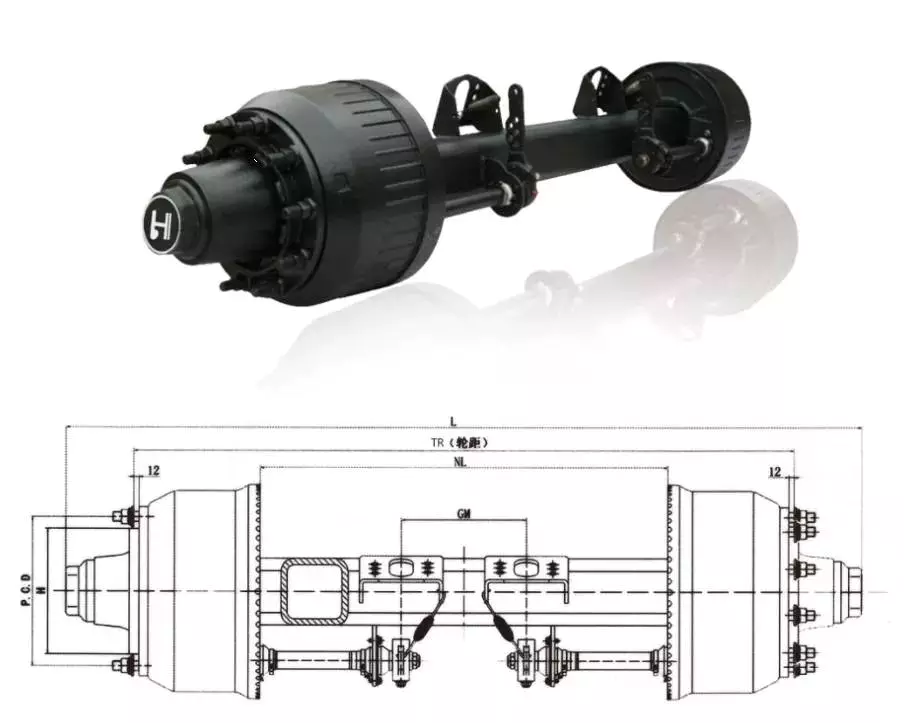
Czpt axles
Czpt axles are available in a variety of configurations. From beam-to-independent designs to single-point-to-double-point designs, there’s a Czpt axle to fit your needs. These axles are designed to provide maximum power in a small package. Czpt has a proven track record of innovation and durability.
Czpt axles are found in front-end steering vehicles and heavy-duty pickups. Some models only use the front axle. There are also Czpt axles for light-duty pickups. You can easily recognize a Czpt axle by its shape. Some online sources offer diagrams to help you identify the axle.
Among the most popular Czpt axles are the Czpt 60 and the Czpt 44. Both models are desirable in their own right. You can order Czpt axle parts from the Czpt website. These products include u joints, differential cases, and loc pins. These parts can be purchased online, and they will be delivered right to your door.
In addition to the Czpt 60 front axle, Czpt axles also feature great aftermarket support. They can be upgraded with locking differentials, limited slip differentials, and high-capacity differential covers. They also feature heat-sinks that keep the axle cool. Czpt axles are also compatible with nearly every traction aid in the market.
Czpt is a global leader in driveline products and genuine service parts. With over a century of experience manufacturing quality products, Czpt axles provide performance and reliability.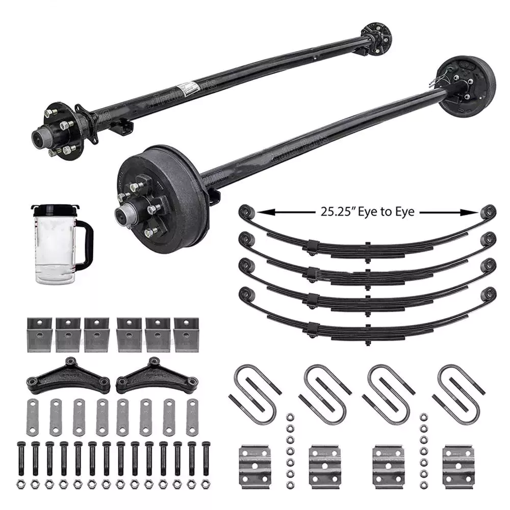
Drop out axles
Drop out axles are crucial for mounting a front wheel to a bike. If the axles are not present, the wheel will not be able to be mounted. These dropouts are made of either steel or aluminum. They are 5.8mm thick. Axles with quick release axle hubs are compatible with steel dropouts.
Axle manufacturers make different dropout axles that are compatible with different axle sizes. These axles are available in a wide range of styles. The Shimano modular dropout, for example, is available in three main axle specifications: Road, Track, and Maxle. These dropouts are also available with different axle pinions.
Drop out axles can be quick release or through. Quick release axles are lighter than thru axles. They weigh approximately 60 to 80 grams. The difference between quick release and thru axles is in the thread pitch. Quick release axles have a smaller pitch than thru axles, which allows for easier installation and removal.
Thru axles are a popular choice for mountain bikes. They prevent the front wheel from coming out while riding. They are more secure and can prevent a wheel from coming off when moving. They are usually made of a thicker rod and screw into the frame. Both types of dropouts have their advantages and disadvantages. You should choose the type that works best for your needs. This is a decision that you will have to make on your own.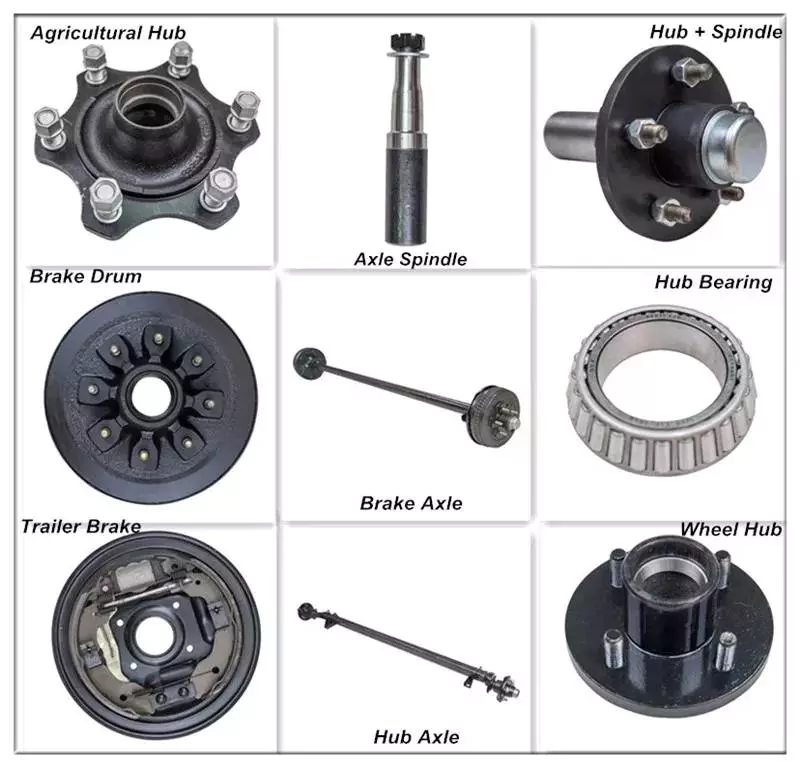
CV joints
When your vehicle is in motion, the CV joints on your axle transfer torque to the wheels. Although these joints come in a wide variety of designs, they all contain a bearing assembly that allows them to move. These joints are protected by a rubber boot that is filled with grease to keep them lubricated. When they become worn, they can cause your car to shudder and vibrate while accelerating.
To avoid joint failure, it is important to keep the CV joints free of road debris. Luckily, the boots are made of durable rubber, and a good quality one can last 100,000 miles. Unfortunately, if the rubber boot is torn, dirt and moisture can leak into the joint. Therefore, it’s important to inspect the boots regularly, and replace them if necessary.
Damaged CV joints can make control of your vehicle extremely difficult. They can also cause your steering wheel to jerk when you’re accelerating, increasing the risk of an accident. A damaged CV joint can also lead to axle separation, which can cause massive damage and a serious safety risk. However, if you don’t have the funds to replace the joint, you can repair the problem by applying a sleeve.
Unlike other drive systems, CV axles can transfer torque at an angle. This is possible because of the constant velocity joints. They’re akin to the univeersal joints on tail shafts, except they work on a much larger angle. This allows the drive shaft to transfer torque to the front wheels smoothly. It also allows the axle to move up and down.
A damaged CV axle will make a characteristic clicking sound when you’re turning the vehicle. This noise is very distinctive and can only be heard when the vehicle is in motion. If you hear this noise, then the joint is worn and is in danger of failure. If this noise is loud and consistent, you’ll need to replace it.

editor by czh 2022-12-12
China Good quality The Cardan Shafts on Steel Rolling Equipment near me factory
Product Description
HangZhou Xihu (West Lake) Dis. Cardanshaft Co.,LTD is a leading professional manufacturer of cardan shafts in China. It is located in HangZhou ,ZheJiang Province. Our company has focused on the research and development , design and manufacture with different kinds of cardan shafts for almost 15 years.
Our producted cardan shafts are widely used in domestic large steel enterprises, such as ZheJiang Baosteel, HangZhou Iron and Steel Corporation, HangZhou Steel Corp and other domestic large-scale iron and steel enterprises.Now more products are exported to Europe, North America and Southeast Asia and other regions.
Our cardan shafts can be used to resist vibration and impact in the harsh environment of steel rolling, and the service life of cardan shafts is longer. We can also customize the special connection modes of cardan shafts in accordance of customers’ requirements .High precision, flexible joints, easy installation, perfect after-sales service and so on are highlight features of our products.
The following table for SWC Medium-sized Universal Shaft Parameters.
Designs
Data and Sizes of SWCZ Series Universal Joint Couplings
| Type | Design Data Item |
SWC160 | SWC180 | SWC200 | SWC225 | SWC250 | SWC265 | SWC285 | SWC315 | SWC350 | SWC390 | SWC440 | SWC490 | SWC550 | SWC620 |
| A | L | 740 | 800 | 900 | 1000 | 1060 | 1120 | 1270 | 1390 | 1520 | 1530 | 1690 | 1850 | 2060 | 2280 |
| LV | 100 | 100 | 120 | 140 | 140 | 140 | 140 | 140 | 150 | 170 | 190 | 190 | 240 | 250 | |
| M(kg) | 65 | 83 | 115 | 152 | 219 | 260 | 311 | 432 | 610 | 804 | 1122 | 1468 | 2154 | 2830 | |
| B | L | 480 | 530 | 590 | 640 | 730 | 790 | 840 | 930 | 100 | 1571 | 1130 | 1340 | 1400 | 1520 |
| M(kg) | 44 | 60 | 85 | 110 | 160 | 180 | 226 | 320 | 440 | 590 | 820 | 1090 | 1560 | 2100 | |
| C | L | 380 | 420 | 480 | 500 | 560 | 600 | 640 | 720 | 782 | 860 | 1040 | 1080 | 1220 | 1360 |
| M(kg) | 35 | 48 | 66 | 90 | 130 | 160 | 189 | 270 | 355 | 510 | 780 | 970 | 1330 | 1865 | |
| D | L | 520 | 580 | 620 | 690 | 760 | 810 | 860 | 970 | 1030 | 1120 | 1230 | 1360 | 1550 | 1720 |
| M(kg) | 48 | 65 | 90 | 120 | 173 | 220 | 250 | 355 | 485 | 665 | 920 | 1240 | 1765 | 2390 | |
| E | L | 800 | 850 | 940 | 1050 | 1120 | 1180 | 1320 | 1440 | 1550 | 1710 | 1880 | 2050 | 2310 | 2540 |
| LV | 100 | 100 | 120 | 140 | 140 | 140 | 140 | 140 | 150 | 170 | 190 | 190 | 240 | 250 | |
| M(kg) | 70 | 92 | 126 | 165 | 238 | 280 | 340 | 472 | 660 | 886 | 1230 | 1625 | 2368 | 3135 | |
| Tn(kN·m) | 16 | 22.4 | 31.5 | 40 | 63 | 80 | 90 | 125 | 180 | 250 | 355 | 500 | 710 | 1000 | |
| TF(kN·m) | 8 | 11.2 | 16 | 20 | 31.5 | 40 | 45 | 63 | 90 | 125 | 180 | 250 | 355 | 500 | |
| Β(°) | 15 | 15 | 15 | 15 | 15 | 15 | 15 | 15 | 15 | 15 | 15 | 15 | 15 | 15 | |
| D | 160 | 180 | 200 | 225 | 250 | 265 | 285 | 315 | 350 | 390 | 440 | 490 | 550 | 620 | |
| Df | 160 | 180 | 200 | 225 | 250 | 265 | 285 | 315 | 350 | 3690 | 440 | 490 | 550 | 620 | |
| D1 | 137 | 155 | 170 | 196 | 218 | 233 | 245 | 280 | 310 | 345 | 390 | 435 | 492 | 555 | |
| D2(H9) | 100 | 105 | 120 | 135 | 150 | 160 | 170 | 185 | 210 | 235 | 255 | 275 | 320 | 380 | |
| D3 | 108 | 114 | 140 | 159 | 168 | 180 | 194 | 219 | 245 | 273 | 299 | 325 | 402 | 426 | |
| Lm | 95 | 105 | 110 | 125 | 140 | 150 | 160 | 180 | 195 | 215 | 260 | 270 | 305 | 340 | |
| K | 16 | 17 | 18 | 20 | 25 | 25 | 27 | 32 | 35 | 40 | 42 | 47 | 50 | 55 | |
| T | 4 | 5 | 5 | 5 | 6 | 6 | 7 | 8 | 8 | 8 | 10 | 12 | 12 | 12 | |
| N | 8 | 8 | 8 | 8 | 8 | 8 | 8 | 10 | 10 | 10 | 16 | 16 | 16 | 16 | |
| D | 15 | 17 | 17 | 17 | 19 | 19 | 21 | 23 | 23 | 25 | 28 | 31 | 31 | 38 | |
| B | 20 | 24 | 32 | 32 | 40 | 40 | 40 | 40 | 50 | 70 | 80 | 90 | 100 | 100 | |
| G | 6.0 | 7.0 | 9.0 | 9.0 | 12.5 | 12.5 | 12.5 | 15.0 | 16.0 | 18.0 | 20.0 | 22.5 | 22.5 | 25 | |
| MI(Kg) | 2.57 | 3 | 3.85 | 3.85 | 5.17 | 6 | 6.75 | 8.25 | 10.6 | 13 | 18.50 | 23.75 | 29.12 | 38.08 | |
| Size | M14 | M16 | M16 | M16 | M18 | M18 | M20 | M22 | M22 | M24 | M27 | M30 | M30 | M36 | |
| Tightening torque(Nm) | 180 | 270 | 270 | 270 | 372 | 372 | 526 | 710 | 710 | 906 | 1340 | 1820 | 1820 | 3170 |
1. Notations:
L=Standard length, or compressed length for designs with length compensation;
LV=Length compensation;
M=Weight;
Tn=Nominal torque(Yield torque 50% over Tn);
TF=Fatigue torque, I. E. Permissible torque as determined according to the fatigue strength
Under reversing loads;
Β=Maximum deflection angle;
MI=weight per 100mm tube
2. Millimeters are used as measurement units except where noted;
3. Please consult us for customizations regarding length, length compensation and
Flange connections.
(DIN or SAT etc. )
Screw Shaft Types
A screw shaft is a cylindrical part that turns. Depending on its size, it is able to drive many different types of devices. The following information outlines the different types of screws, including their sizes, material, function, and applications. To help you select the right screw shaft, consider the following factors:
Size
A screw can come in a variety of shapes and sizes, ranging from a quarter to a quarter-inch in diameter. A screw is a cylindrical shaft with an inclined plane wrapped around it, and its main function is to fasten objects together by translating torque into a linear force. This article will discuss the dimensions of screws and how to determine the size of a screw. It is important to note that screw sizes can be large and small depending on the purpose.
The diameter of a screw is the diameter of its shaft, and it must match the inner diameter of its nuts and washers. Screws of a certain diameter are also called machine screws, and they can be larger or smaller. Screw diameters are measured on the shaft underneath the screw head. The American Society of Mechanical Engineers (ASME) standardized screw diameters in 3/50-inch to 16 (3/8-inch) inches, and more recently, sizes were added in U.S. fractions of an inch. While shaft and head diameters are standardized, screw length may vary from job to job.
In the case of the 2.3-mm screw group, the construct strength was not improved by the 1.2-mm group. The smaller screw size did not increase the strength of the construct. Further, ABS material did not improve the construct strength. Thus, the size of screw shaft is an important consideration in model design. And remember that the more complex your model is, the larger it will be. A screw of a given size will have a similar failure rate as a screw of a different diameter.
Although different screw sizes are widely used, the differences in screw size were not statistically significant. Although there are some limitations, screws of different sizes are generally sufficient for fixation of a metacarpal shaft fracture. However, further clinical studies are needed to compare screw sizes for fracture union rates. So, if you are unsure of what size of screw shaft you need for your case, make sure to check the metric chart and ensure you use the right one.
Material
The material of a screw shaft plays an important role in the overall performance of a screw. Axial and central forces act to apply torque to the screw, while external forces, such as friction, exert a bending moment. The torsional moments are reflected in the torque, and this causes the screw to rotate at a higher rate than necessary. To ensure the longevity of the screw, the material of the screw shaft should be able to handle the bending moment, while the diameter of the shaft should be small enough to avoid causing damage.
Screws are made from different metals, such as steel, brass, titanium, and bronze. Manufacturers often apply a top coating of chromium, brass, or zinc to improve corrosion resistance. Screws made of aluminum are not durable and are prone to rusting due to exposure to weather conditions. The majority of screw shafts are self-locking. They are suited for many applications, including threaded fasteners, C-clamps, and vises.
Screws that are fabricated with conical sections typically feature reduced open cross-sectional areas at the discharge point. This is a key design parameter of conical screw shafts. In fact, reductions of up to 72% are common across a variety of applications. If the screw is designed to have a hard-iron hanger bearing, it must be hardened. If the screw shaft is not hardened, it will require an additional lubricant.
Another consideration is the threads. Screw shafts are typically made of high-precision threads and ridges. These are manufactured on lathes and CNC machines. Different shapes require different materials. Materials for the screw shaft vary. There are many different sizes and shapes available, and each 1 has its own application. In addition to helical and conical screw shafts, different materials are also available. When choosing material, the best 1 depends on the application.
The life of the screw depends on its size, load, and design. In general, the material of the screw shaft, nut body, and balls and rollers determine its fatigue life. This affects the overall life of the screw. To determine whether a specific screw has a longer or shorter life, the manufacturer must consider these factors, as well as the application requirements. The material should be clean and free of imperfections. It should be smooth and free of cracks or flaking, which may result in premature failure.
Function
The function of a screw shaft is to facilitate the rotation of a screw. Screws have several thread forms, including single-start, double-start and multi-start. Each form has its own advantages and disadvantages. In this article we’ll explore each of them in detail. The function of a screw shaft can vary based on its design, but the following are common types. Here are some examples of screw shaft types and their purposes.
The screw’s torque enables it to lift objects. It can be used in conjunction with a bolt and nut to lift a load. Screws are also used to secure objects together. You can use them in screw presses, vises, and screw jacks. But their primary function is to hold objects together. Listed below are some of their main functions. When used to lift heavy loads, they can provide the required force to secure an object.
Screws can be classified into 2 types: square and round. Square threads are more efficient than round ones because they apply 0deg of angle to the nut. Square threads are also stronger than round threads and are often used in high-load applications. They’re generally cheaper to manufacture and are more difficult to break. And unlike square threads, which have a 0deg thread angle, these threads can’t be broken easily with a screwdriver.
A screw’s head is made of a series of spiral-like structures that extend from a cylindrical part to a tip. This portion of the screw is called the shank and is made of the smallest area. The shank is the portion that applies more force to the object. As the shaft extends from the head, it becomes thinner and narrow, forming a pointed tip. The head is the most important part of the screw, so it needs to be strong to perform its function.
The diameter of the screw shaft is measured in millimeters. The M8 screw has a thread pitch of 1.25 mm. Generally, the size of the screw shaft is indicated by the major and minor diameter. These dimensions are appended with a multiplication sign (M8x1).
Applications
The design of screws, including their size and shape, determines their critical rotating speeds. These speeds depend on the threaded part of the screw, the helix angle, and the geometry of the contact surfaces. When applied to a screw, these limits are referred to as “permissible speed limits.” These maximum speeds are meant for short periods of time and optimized running conditions. Continuous operation at these speeds can reduce the calculated life of a nut mechanism.
The main materials used to manufacture screws and screw shafts include steel, stainless steel, titanium, bronze, and brass. Screws may be coated for corrosion resistance, or they may be made of aluminium. Some materials can be threaded, including Teflon and nylon. Screw threads can even be molded into glass or porcelain. For the most part, steel and stainless steel are the most common materials for screw shafts. Depending on the purpose, a screw will be made of a material that is suitable for the application.
In addition to being used in fasteners, screw shafts are used in micrometers, drillers, conveyor belts, and helicopter blades. There are numerous applications of screw shafts, from weighing scales to measuring lengths. If you’re in the market for a screw, make sure to check out these applications. You’ll be happy you did! They can help you get the job done faster. So, don’t delay your next project.
If you’re interested in learning about screw sizing, then it’s important to know the axial and moment loads that your screws will experience. By following the laws of mechanics and knowing the load you can calculate the nominal life of your screw. You can also consider the effect of misalignment, uneven loading, and shocks on your screw. These will all affect the life of your screw. Then, you can select the right screw.
China wholesaler Cardan Shafts/Universal Shafts for Rubber Machinery with high quality
Product Description
Production description
Almost 15 years,Xihu (West Lake) Dis. has focused on the research and development, design and manufacture of cardan shafts on the rubber machinery. Our producted cardan shafts are widely used by rubber and plastic machinery manufacturer, famous for example, HangZhou Hua Han Plastic Machinery Co. Ltd.; HangZhou Rubber & Plastics Machinery Group, HangZhou DoubleStar Rubber Machinery Co. Ltd., ZheJiang dedicated machinery Co. Ltd. and other large domestic rubber machinery production enterprises.
Now it is out of the country, the products are exported to Europe, North America and Southeast Asia and other regions. Designation of the universal shafts used in rolling machine, mixer, open rubber mixing machine. Our cardan shafts with the features such as, anti vibration, anti impact in the bad environment, anti dust corrosion, long service life,no need more maintenance, lengthened the cardan shaft repair cycle. According to customer requirements ,we can also customize the special connection mode of universal shafts with high coaxial, flexible joints, easy installation, perfect after-sales service.
The following table for SWC Medium-sized Universal Shaft Parameters.
Designs
Data and Sizes of SWCZ Series Universal Joint Couplings
| Type | Design Data Item |
SWC160 | SWC180 | SWC200 | SWC225 | SWC250 | SWC265 | SWC285 | SWC315 | SWC350 | SWC390 | SWC440 | SWC490 | SWC550 | SWC620 |
| A | L | 740 | 800 | 900 | 1000 | 1060 | 1120 | 1270 | 1390 | 1520 | 1530 | 1690 | 1850 | 2060 | 2280 |
| LV | 100 | 100 | 120 | 140 | 140 | 140 | 140 | 140 | 150 | 170 | 190 | 190 | 240 | 250 | |
| M(kg) | 65 | 83 | 115 | 152 | 219 | 260 | 311 | 432 | 610 | 804 | 1122 | 1468 | 2154 | 2830 | |
| B | L | 480 | 530 | 590 | 640 | 730 | 790 | 840 | 930 | 100 | 1571 | 1130 | 1340 | 1400 | 1520 |
| M(kg) | 44 | 60 | 85 | 110 | 160 | 180 | 226 | 320 | 440 | 590 | 820 | 1090 | 1560 | 2100 | |
| C | L | 380 | 420 | 480 | 500 | 560 | 600 | 640 | 720 | 782 | 860 | 1040 | 1080 | 1220 | 1360 |
| M(kg) | 35 | 48 | 66 | 90 | 130 | 160 | 189 | 270 | 355 | 510 | 780 | 970 | 1330 | 1865 | |
| D | L | 520 | 580 | 620 | 690 | 760 | 810 | 860 | 970 | 1030 | 1120 | 1230 | 1360 | 1550 | 1720 |
| M(kg) | 48 | 65 | 90 | 120 | 173 | 220 | 250 | 355 | 485 | 665 | 920 | 1240 | 1765 | 2390 | |
| E | L | 800 | 850 | 940 | 1050 | 1120 | 1180 | 1320 | 1440 | 1550 | 1710 | 1880 | 2050 | 2310 | 2540 |
| LV | 100 | 100 | 120 | 140 | 140 | 140 | 140 | 140 | 150 | 170 | 190 | 190 | 240 | 250 | |
| M(kg) | 70 | 92 | 126 | 165 | 238 | 280 | 340 | 472 | 660 | 886 | 1230 | 1625 | 2368 | 3135 | |
| Tn(kN·m) | 16 | 22.4 | 31.5 | 40 | 63 | 80 | 90 | 125 | 180 | 250 | 355 | 500 | 710 | 1000 | |
| TF(kN·m) | 8 | 11.2 | 16 | 20 | 31.5 | 40 | 45 | 63 | 90 | 125 | 180 | 250 | 355 | 500 | |
| Β(°) | 15 | 15 | 15 | 15 | 15 | 15 | 15 | 15 | 15 | 15 | 15 | 15 | 15 | 15 | |
| D | 160 | 180 | 200 | 225 | 250 | 265 | 285 | 315 | 350 | 390 | 440 | 490 | 550 | 620 | |
| Df | 160 | 180 | 200 | 225 | 250 | 265 | 285 | 315 | 350 | 3690 | 440 | 490 | 550 | 620 | |
| D1 | 137 | 155 | 170 | 196 | 218 | 233 | 245 | 280 | 310 | 345 | 390 | 435 | 492 | 555 | |
| D2(H9) | 100 | 105 | 120 | 135 | 150 | 160 | 170 | 185 | 210 | 235 | 255 | 275 | 320 | 380 | |
| D3 | 108 | 114 | 140 | 159 | 168 | 180 | 194 | 219 | 245 | 273 | 299 | 325 | 402 | 426 | |
| Lm | 95 | 105 | 110 | 125 | 140 | 150 | 160 | 180 | 195 | 215 | 260 | 270 | 305 | 340 | |
| K | 16 | 17 | 18 | 20 | 25 | 25 | 27 | 32 | 35 | 40 | 42 | 47 | 50 | 55 | |
| T | 4 | 5 | 5 | 5 | 6 | 6 | 7 | 8 | 8 | 8 | 10 | 12 | 12 | 12 | |
| N | 8 | 8 | 8 | 8 | 8 | 8 | 8 | 10 | 10 | 10 | 16 | 16 | 16 | 16 | |
| D | 15 | 17 | 17 | 17 | 19 | 19 | 21 | 23 | 23 | 25 | 28 | 31 | 31 | 38 | |
| B | 20 | 24 | 32 | 32 | 40 | 40 | 40 | 40 | 50 | 70 | 80 | 90 | 100 | 100 | |
| G | 6.0 | 7.0 | 9.0 | 9.0 | 12.5 | 12.5 | 12.5 | 15.0 | 16.0 | 18.0 | 20.0 | 22.5 | 22.5 | 25 | |
| MI(Kg) | 2.57 | 3 | 3.85 | 3.85 | 5.17 | 6 | 6.75 | 8.25 | 10.6 | 13 | 18.50 | 23.75 | 29.12 | 38.08 | |
| Size | M14 | M16 | M16 | M16 | M18 | M18 | M20 | M22 | M22 | M24 | M27 | M30 | M30 | M36 | |
| Tightening torque(Nm) | 180 | 270 | 270 | 270 | 372 | 372 | 526 | 710 | 710 | 906 | 1340 | 1820 | 1820 | 3170 |
1. Notations:
L=Standard length, or compressed length for designs with length compensation;
LV=Length compensation;
M=Weight;
Tn=Nominal torque(Yield torque 50% over Tn);
TF=Fatigue torque, I. E. Permissible torque as determined according to the fatigue strength
Under reversing loads;
β=Maximum deflection angle;
MI=weight per 100mm tube
2. Millimeters are used as measurement units except where noted;
3. Please consult us for customizations regarding length, length compensation and
Flange connections.
(DIN or SAT etc. )
The 5 components of an axle, their function and installation
If you’re considering replacing an axle in your vehicle, you should first understand what it is. It is the component that transmits electricity from 1 part to another. Unlike a fixed steering wheel, the axles are movable. The following article will discuss the 5 components of the half shaft, their function and installation. Hopefully you were able to identify the correct axle for your vehicle. Here are some common problems you may encounter along the way.
five components
The 5 components of the shaft are flange, bearing surface, spline teeth, spline pitch and pressure angle. The higher the number of splines, the stronger the shaft. The maximum stress that the shaft can withstand increases with the number of spline teeth and spline pitch. The diameter of the shaft times the cube of the pressure angle and spline pitch determines the maximum stress the shaft can withstand. For extreme load applications, use axles made from SAE 4340 and SAE 1550 materials. In addition to these 2 criteria, spline rolling produces a finer grain structure in the material. Cutting the splines reduces the strength of the shaft by 30% and increases stress.
The asymmetric length of the shaft implies different torsional stiffness. A longer shaft, usually the driver’s side, can handle more twist angles before breaking. When the long axis is intact, the short axis usually fails, but this does not always happen. Some vehicles have short axles that permanently break, causing the same failure rate for both. It would be ideal if both shafts were the same length, they would share the same load.
In addition to the spline pitch, the diameter of the shaft spline is another important factor. The small diameter of a spline is the radius at which it resists twisting. Therefore, the splines must be able to absorb shock loads and shocks while returning to their original shape. To achieve these goals, the spline pitch should be 30 teeth or less, which is standard on Chrysler 8.75-inch and GM 12-bolt axles. However, a Ford 8.8-inch axle may have 28 or 31 tooth splines.
In addition to the CV joints, the axles also include CV joints, which are located on each end of the axle. ACV joints, also known as CV joints, use a special type of bearing called a pinion. This is a nut that meshes with the side gear to ensure proper shaft alignment. If you notice a discrepancy, take your car to a shop and have it repaired immediately.
Function
Axles play several important roles in a vehicle. It transfers power from the transmission to the rear differential gearbox and the wheels. The shaft is usually made of steel with cardan joints at both ends. Shaft Shafts can be stationary or rotating. They are all creatures that can transmit electricity and loads. Here are some of their functions. Read on to learn more about axles. Some of their most important features are listed below.
The rear axle supports the weight of the vehicle and is connected to the front axle through the axle. The rear axle is suspended from the body, frame and axle housing, usually spring loaded, to cushion the vehicle. The driveshaft, also called the propshaft, is located between the rear wheels and the differential. It transfers power from the differential to the drive wheels.
The shaft is made of mild steel or alloy steel. The latter is stronger, more corrosion-resistant and suitable for special environments. Forged for large diameter shafts. The cross section of the shaft is circular. While they don’t transmit torque, they do transmit bending moment. This allows the drive train to rotate. If you’re looking for new axles, it’s worth learning more about how they work.
The shaft consists of 3 distinct parts: the main shaft and the hub. The front axle assembly has a main shaft, while the rear axle is fully floating. Axles are usually made of chrome molybdenum steel. The alloy’s chromium content helps the axle maintain its tensile strength even under extreme conditions. These parts are welded into the axle housing.
Material
The material used to make the axle depends on the purpose of the vehicle. For example, overload shafts are usually made of SAE 4340 or 1550 steel. These steels are high strength low alloy alloys that are resistant to bending and buckling. Chromium alloys, for example, are made from steel and have chromium and molybdenum added to increase their toughness and durability.
The major diameter of the shaft is measured at the tip of the spline teeth, while the minor diameter is measured at the bottom of the groove between the teeth. These 2 diameters must match, otherwise the half shaft will not work properly. It is important to understand that the brittleness of the material should not exceed what is required to withstand normal torque and twisting, otherwise it will become unstable. The material used to make the axles should be strong enough to carry the weight of a heavy truck, but must also be able to withstand torque while still being malleable.
Typically, the shaft is case hardened using an induction process. Heat is applied to the surface of the steel to form martensite and austenite. The shell-core interface transitions from compression to tension, and the peak stress level depends on the process variables used, including heating time, residence time, and hardenability of the steel. Some common materials used for axles are listed below. If you’re not sure which material is best for your axle, consider the following guide.
The axle is the main component of the axle and transmits the transmission motion to the wheels. In addition, they regulate the drive between the rear hub and the differential sun gear. The axle is supported by axle bearings and guided to the path the wheels need to follow. Therefore, they require proper materials, processing techniques and thorough inspection methods to ensure lasting performance. You can start by selecting the material for the shaft.
Choosing the right alloy for the axle is critical. You will want to find an alloy with a low carbon content so it can harden to the desired level. This is an important consideration because the hardenability of the alloy is important to the durability and fatigue life of the axle. By choosing the right alloy, you will be able to minimize these problems and improve the performance of your axle. If you have no other choice, you can always choose an alloy with a higher carbon content, but it will cost you more money.
Install
The process of installing a new shaft is simple. Just loosen the axle nut and remove the set bolt. You may need to tap a few times to get a good seal. After installation, check the shaft at the points marked “A” and “D” to make sure it is in the correct position. Then, press the “F” points on the shaft flange until the points are within 0.002″ of the runout.
Before attempting to install the shaft, check the bearings to make sure they are aligned. Some bearings may have backlash. To determine the amount of differential clearance, use a screwdriver or clamp lever to check. Unless it’s caused by a loose differential case hub, there shouldn’t be any play in the axle bearings. You may need to replace the differential case if the axles are not mounted tightly. Thread adjusters are an option for adjusting drive gear runout. Make sure the dial indicator is mounted on the lead stud and loaded so that the plunger is at right angles to the drive gear.
To install the axle, lift the vehicle with a jack or crane. The safety bracket should be installed under the frame rails. If the vehicle is on a jack, the rear axle should be in the rebound position to ensure working clearance. Label the drive shaft assemblies and reinstall them in their original positions. Once everything is back in place, use a 2-jaw puller to pry the yoke and flange off the shaft.
If you’ve never installed a half shaft before, be sure to read these simple steps to get it right. First, check the bearing surfaces to make sure they are clean and undamaged. Replace them if they look battered or dented. Next, remove the seal attached to the bushing hole. Make sure the shaft is installed correctly and the bearing surfaces are level. After completing the installation process, you may need to replace the bearing seals.
China factory Swp Type Cardan Drive Shafts with Bolts on The Flange near me shop
Product Description
SWC cardan shaft for rolling mill
Cardan shaft is a mechanical component for transmitting torque and rotation, usually used to connect driving motor and operation machines that cannot be connected directly because of distance or the need to allow for relative movement between them.
Product Show
Technical Data
| NO | D mm |
Tn kN.m |
Tf kN.m |
β | Size | Rotational inertia kg.m2 |
M kg |
|||||
| LS mm |
Lmin | D3 | Lm | Lmin | Increase 100mm | Lmin | Increase 100mm | |||||
| SWC180BF | 180 | 20 | 10 | ≤25 | 100 | 810 | 114 | 110 | 0.267 | 0.0070 | 80 | 2.8 |
| SWC225BF | 225 | 40 | 20 | ≤15 | 140 | 920 | 152 | 120 | 0.778 | 0.5714 | 138 | 4.9 |
| SWC250BF | 250 | 63 | 31.5 | ≤15 | 140 | 1035 | 168 | 140 | 1.445 | 0.5717 | 196 | 5.3 |
| SWC285BF | 285 | 90 | 45 | ≤15 | 140 | 1190 | 194 | 160 | 2.873 | 0.571 | 295 | 6.3 |
| SWC315BF | 315 | 125 | 63 | ≤15 | 140 | 1315 | 219 | 180 | 5.094 | 0.571 | 428 | 8.0 |
| SWC350BF | 350 | 180 | 90 | ≤15 | 150 | 1410 | 267 | 194 | 9.195 | 0.2219 | 632 | 15.0 |
| SWC390BF | 390 | 250 | 125 | ≤15 | 170 | 1590 | 267 | 215 | 16.62 | 0.2219 | 817 | 15.0 |
| SWC440BF | 440 | 355 | 180 | ≤15 | 190 | 1875 | 325 | 260 | 28.24 | 0.4744 | 1290 | 21.7 |
| SWC490BF | 490 | 500 | 250 | ≤15 | 190 | 1985 | 325 | 270 | 46.33 | 0.4744 | 1631 | 21.7 |
| SWC550BF | 550 | 710 | 355 | ≤15 | 240 | 2300 | 426 | 305 | 86.98 | 1.3570 | 2567 | 34.0 |
| SWC620BF | 620 | 1000 | 500 | ≤15 | 240 | 2500 | 426 | 340 | 147.50 | 1.357 | 3267 | 34.0 |
Huading Cardan Universal Shaft Features:
1. We offer over 1000 different spare parts for a wide range of agricultural machinery, from combine harvesters, mowers,rakes to balers.They are used for various makes like John Deere, LAVERDA ,Claas, CZPT and Case/IH. 2.Elastomer connecting in the middle
3.Can absorb vibration, compensates for radial, axial and angular deviation
4.Oil resistance and electrical insulation
5.Have the same characteristic of clockwise and anticlockwise rotation
Cardan Shaft Types
We can supply you SWP,SWC,WSD,WS universal coupling as following:
Welded shaft type with length compensation / expansion joint
Short type with length compensation / expansion joint
Short type without length compensation / expansion joint
Long type without length compensation / expansion joint
Double flange with length compensation / expansion joint
Long type with big length compensation / big expansion joint
Super Short type with length compensation / expansion joint
Our Company
HangZhou CZPT Machinery Manufacturing Co., Ltd. Is a high-tech enterprise specializing in the design and manufacture of various types of coupling. There are 86 employees in our company, including 2 senior engineers and no fewer than 20 mechanical design and manufacture, heat treatment, welding and other professionals. Advanced and reasonable process, complete detection means. We company actively introduce foreign advanced technology and equipment, on the basis of the condition, we make full use of the advantage and do more research and innovation. Strict to high quality and operate strictly in accordance with the ISO9000 quality certification system standard mode.
The leading products of the company are mainly universal coupling, gear coupling, flexible coupling, rigid coupling and other series of dozens of thousands of specifications coupling, widely used in metallurgy, mining, lifting transport, petroleum chemical industry, papermaking, pharmaceutical, textile, printing and dyeing, ships, locomotives and equipment, longitudinal welded pipe cut, HangZhou, straightening and other industries, it provide strong support of technology and equipment for the localization of imported domestic numerous couplings, won the praise of clients.
Our Services
1.Design Services
Our design team has experience in cardan shaft relating to product design and development. If you have any needs for your new product or wish to make further improvements, we are here to offer our support.
2.Product Services
raw materials → Cutting → Forging →Rough machining →Shot blasting →Heat treatment →Testing →Fashioning →Cleaning→ Assembly→Packing→Shipping
3.Samples Procedure
We could develop the sample according to your requirement and amend the sample constantly to meet your need.
4.Research & Development
We usually research the new needs of the market and develop the new model when there is new cars in the market.
5.Quality Control
Every step should be special test by Professional Staff according to the standard of ISO9001 and TS16949.
Products List
| Transmission Machinery Parts Name | Model |
| universal coupling | WS WSD WSP |
| cardan shaft | SWC SWP SWZ |
| tooth coupling | CL CLZ GCLD GIICL GICL NGCL GGCL PGCLK |
| disc coupling | JMI JMIJ JMII JMIIJ |
| high flexible coupling | LM |
| chain coupling | GL |
| jaw coupling | LT |
| grid coupling | JS |
Welcome to customize products from our factory and pls send us more details about your purchasing.
Thank you for your time and attention.
Screw Sizes and Their Uses
Screws have different sizes and features. This article will discuss screw sizes and their uses. There are 2 main types: right-handed and left-handed screw shafts. Each screw features a point that drills into the object. Flat tipped screws, on the other hand, need a pre-drilled hole. These screw sizes are determined by the major and minor diameters. To determine which size of screw you need, measure the diameter of the hole and the screw bolt’s thread depth.
The major diameter of a screw shaft
The major diameter of a screw shaft is the distance from the outer edge of the thread on 1 side to the tip of the other. The minor diameter is the inner smooth part of the screw shaft. The major diameter of a screw is typically between 2 and 16 inches. A screw with a pointy tip has a smaller major diameter than 1 without. In addition, a screw with a larger major diameter will have a wider head and drive.
The thread of a screw is usually characterized by its pitch and angle of engagement. The pitch is the angle formed by the helix of a thread, while the crest forms the surface of the thread corresponding to the major diameter of the screw. The pitch angle is the angle between the gear axis and the pitch surface. Screws without self-locking threads have multiple starts, or helical threads.
The pitch is a crucial component of a screw’s threading system. Pitch is the distance from a given thread point to the corresponding point of the next thread on the same shaft. The pitch line is 1 element of pitch diameter. The pitch line, or lead, is a crucial dimension for the thread of a screw, as it controls the amount of thread that will advance during a single turn.
The pitch diameter of a screw shaft
When choosing the appropriate screw, it is important to know its pitch diameter and pitch line. The pitch line designates the distance between adjacent thread sides. The pitch diameter is also known as the mean area of the screw shaft. Both of these dimensions are important when choosing the correct screw. A screw with a pitch of 1/8 will have a mechanical advantage of 6.3. For more information, consult an application engineer at Roton.
The pitch diameter of a screw shaft is measured as the distance between the crest and the root of the thread. Threads that are too long or too short will not fit together in an assembly. To measure pitch, use a measuring tool with a metric scale. If the pitch is too small, it will cause the screw to loosen or get stuck. Increasing the pitch will prevent this problem. As a result, screw diameter is critical.
The pitch diameter of a screw shaft is measured from the crest of 1 thread to the corresponding point on the next thread. Measurement is made from 1 thread to another, which is then measured using the pitch. Alternatively, the pitch diameter can be approximated by averaging the major and minor diameters. In most cases, the pitch diameter of a screw shaft is equal to the difference between the two.
The thread depth of a screw shaft
Often referred to as the major diameter, the thread depth is the outermost diameter of the screw. To measure the thread depth of a screw, use a steel rule, micrometer, or caliper. In general, the first number in the thread designation indicates the major diameter of the thread. If a section of the screw is worn, the thread depth will be smaller, and vice versa. Therefore, it is good practice to measure the section of the screw that receives the least amount of use.
In screw manufacturing, the thread depth is measured from the crest of the screw to the root. The pitch diameter is halfway between the major and minor diameters. The lead diameter represents the amount of linear distance traveled in 1 revolution. As the lead increases, the load capacity decreases. This measurement is primarily used in the construction of screws. However, it should not be used for precision machines. The thread depth of a screw shaft is essential for achieving accurate screw installation.
To measure the thread depth of a screw shaft, the manufacturer must first determine how much material the thread is exposed to. If the thread is exposed to side loads, it can cause the nut to wedge. Because the nut will be side loaded, its thread flanks will contact the nut. The less clearance between the nut and the screw, the lower the clearance between the nut and the screw. However, if the thread is centralized, there is no risk of the nut wedgeing.
The lead of a screw shaft
Pitch and lead are 2 measurements of a screw’s linear distance per turn. They’re often used interchangeably, but their definitions are not the same. The difference between them lies in the axial distance between adjacent threads. For single-start screws, the pitch is equal to the lead, while the lead of a multi-start screw is greater than the pitch. This difference is often referred to as backlash.
There are 2 ways to calculate the pitch and lead of a screw. For single-start screws, the lead and pitch are equal. Multiple-start screws, on the other hand, have multiple starts. The pitch of a multiple-start screw is the same as its lead, but with 2 or more threads running the length of the screw shaft. A square-thread screw is a better choice in applications requiring high load-bearing capacity and minimal friction losses.
The PV curve defines the safe operating limits of lead screw assemblies. It describes the inverse relationship between contact surface pressure and sliding velocity. As the load increases, the lead screw assembly must slow down in order to prevent irreversible damage from frictional heat. Furthermore, a lead screw assembly with a polymer nut must reduce rpm as the load increases. The more speed, the lower the load capacity. But, the PV factor must be below the maximum allowed value of the material used to make the screw shaft.
The thread angle of a screw shaft
The angle between the axes of a thread and the helix of a thread is called the thread angle. A unified thread has a 60-degree angle in all directions. Screws can have either a tapped hole or a captive screw. The screw pitch is measured in millimeters (mm) and is usually equal to the screw major diameter. In most cases, the thread angle will be equal to 60-degrees.
Screws with different angles have various degrees of thread. Originally, this was a problem because of the inconsistency in the threading. However, Sellers’s thread was easier to manufacture and was soon adopted as a standard throughout the United States. The United States government began to adopt this thread standard in the mid-1800s, and several influential corporations in the railroad industry endorsed it. The resulting standard is called the United States Standard thread, and it became part of the ASA’s Vol. 1 publication.
There are 2 types of screw threads: coarse and fine. The latter is easier to tighten and achieves tension at lower torques. On the other hand, the coarse thread is deeper than the fine one, making it easier to apply torque to the screw. The thread angle of a screw shaft will vary from bolt to bolt, but they will both fit in the same screw. This makes it easier to select the correct screw.
The tapped hole (or nut) into which the screw fits
A screw can be re-threaded without having to replace it altogether. The process is different than that of a standard bolt, because it requires threading and tapping. The size of a screw is typically specified by its major and minor diameters, which is the inside distance between threads. The thread pitch, which is the distance between each thread, is also specified. Thread pitch is often expressed in threads per inch.
Screws and bolts have different thread pitches. A coarse thread has fewer threads per inch and a longer distance between threads. It is therefore larger in diameter and longer than the material it is screwed into. A coarse thread is often designated with an “A” or “B” letter. The latter is generally used in smaller-scale metalworking applications. The class of threading is called a “threaded hole” and is designated by a letter.
A tapped hole is often a complication. There is a wide range of variations between the sizes of threaded holes and nut threads, so the tapped hole is a critical dimension in many applications. However, even if you choose a threaded screw that meets the requisite tolerance, there may be a mismatch in the thread pitch. This can prevent the screw from freely rotating.
China wholesaler SWC-I Series Cardan Shafts/Universal Shafts/Drive Shafts with Hot selling
Product Description
SWC-I Series-Light-Duty Designs Cardan shaft
Designs
Data and Size of SWC-I Series Universal Joint Couplings
| Type | Desian Data Item |
SWC-I 58 |
SWC-I 65 |
SWC-I 75 |
SWC-I 90 |
SWC-I 100 |
SWC-I 120 |
SWC-I 150 |
SWC-I 180 |
SWC-I 200 |
SWC-I 225 |
| A | L | 255 | 285 | 335 | 385 | 445 | 500 | 590 | 640 | 775 | 860 |
| Lv | 35 | 40 | 40 | 45 | 55 | 80 | 80 | 80 | 100 | 120 | |
| m(kg) | 2.2 | 3.0 | 5.0 | 6.6 | 9.5 | 17 | 32 | 40 | 76 | 128 | |
| B | L | 150 | 175 | 200 | 240 | 260 | 295 | 370 | 430 | 530 | 600 |
| m(kg) | 1.7 | 2.4 | 3.8 | 5.7 | 7.7 | 13.1 | 23 | 28 | 55 | 98 | |
| C | L | 128 | 156 | 180 | 208 | 220 | 252 | 340 | 348 | 440 | 480 |
| m(kg) | 1.3 | 1.95 | 3.1 | 5.0 | 7.0 | 12.3 | 22 | 30 | 56 | 96 | |
| Tn(N·m) | 150 | 200 | 400 | 750 | 1250 | 2500 | 4500 | 8400 | 16000 | 22000 | |
| Tf(N·m) | 75 | 100 | 200 | 375 | 630 | 1250 | 2250 | 4200 | 8000 | 11000 | |
| β(°) | 35 | 35 | 35 | 35 | 35 | 35 | 35 | 25 | 25 | 25 | |
| D | 52 | 63 | 72 | 92 | 100 | 112 | 142 | 154 | 187 | 204 | |
| Df | 58 | 65 | 75 | 90 | 100 | 120 | 150 | 180 | 200 | 225 | |
| D1 | 47 | 52 | 62 | 74.5 | 84 | 101.5 | 130 | 155.5 | 170 | 196 | |
| D2(H9) | 30 | 35 | 42 | 47 | 57 | 75 | 90 | 110 | 125 | 140 | |
| D3 | 38 | 38 | 4 | 50 | 60 | 70 | 89 | 102 | 114 | 140 | |
| Lm | 32 | 39 | 45 | 52 | 55 | 63 | 85 | 87 | 110 | 120 | |
| k | 3.5 | 4.5 | 5.5 | 6.0 | 8.0 | 8.0 | 10.0 | 12.0 | 14.0 | 15.0 | |
| t | 1.5 | 1.7 | 2.0 | 2.5 | 2.5 | 2.5 | 3.0 | 4.0 | 4.0 | 5.0 | |
| n | 4 | 4 | 6 | 4 | 6 | 8 | 8 | 8 | 8 | 8 | |
| d | 5.1 | 6.5 | 6.5 | 8.5 | 8.5 | 10.5 | 13 | 15 | 17 | 17 | |
| MI(kg) | 0.14 | 0.16 | 0.38 | 0.38 | 0.53 | 0.53 | 0.87 | 0.87 | 1.65 | 2.14 | |
| Flange bolt | size | M5 | M6 | M6 | M8 | M8 | M10 | M12 | M14 | M16 | M16 |
| Tightening torque(N·m) | 7 | 13 | 13 | 32 | 32 | 64 | 110 | 180 | 270 | 270 |
1. Notations:
L=Standard length, or compressed length for designs with length compensation;
LV=Length compensation;
M=Weight;
Tn=Nominal torque(Yield torque 50% over Tn);
TF=Fatigue torque, I. E. Permissible torque as determined according to the fatigue strength
Under reversing loads;
β=Maximum deflection angle;
MI=weight per 100mm tube
2. Millimeters are used as measurement units except where noted;
3. Please consult us for customizations regarding length, length compensation and
Flange connections.
How to Determine the Quality of a Worm Shaft
There are many advantages of a worm shaft. It is easier to manufacture, as it does not require manual straightening. Among these benefits are ease of maintenance, reduced cost, and ease of installation. In addition, this type of shaft is much less prone to damage due to manual straightening. This article will discuss the different factors that determine the quality of a worm shaft. It also discusses the Dedendum, Root diameter, and Wear load capacity.
Root diameter
There are various options when choosing worm gearing. The selection depends on the transmission used and production possibilities. The basic profile parameters of worm gearing are described in the professional and firm literature and are used in geometry calculations. The selected variant is then transferred to the main calculation. However, you must take into account the strength parameters and the gear ratios for the calculation to be accurate. Here are some tips to choose the right worm gearing.
The root diameter of a worm gear is measured from the center of its pitch. Its pitch diameter is a standardized value that is determined from its pressure angle at the point of zero gearing correction. The worm gear pitch diameter is calculated by adding the worm’s dimension to the nominal center distance. When defining the worm gear pitch, you have to keep in mind that the root diameter of the worm shaft must be smaller than the pitch diameter.
Worm gearing requires teeth to evenly distribute the wear. For this, the tooth side of the worm must be convex in the normal and centre-line sections. The shape of the teeth, referred to as the evolvent profile, resembles a helical gear. Usually, the root diameter of a worm gear is more than a quarter inch. However, a half-inch difference is acceptable.
Another way to calculate the gearing efficiency of a worm shaft is by looking at the worm’s sacrificial wheel. A sacrificial wheel is softer than the worm, so most wear and tear will occur on the wheel. Oil analysis reports of worm gearing units almost always show a high copper and iron ratio, suggesting that the worm’s gearing is ineffective.
Dedendum
The dedendum of a worm shaft refers to the radial length of its tooth. The pitch diameter and the minor diameter determine the dedendum. In an imperial system, the pitch diameter is referred to as the diametral pitch. Other parameters include the face width and fillet radius. Face width describes the width of the gear wheel without hub projections. Fillet radius measures the radius on the tip of the cutter and forms a trochoidal curve.
The diameter of a hub is measured at its outer diameter, and its projection is the distance the hub extends beyond the gear face. There are 2 types of addendum teeth, 1 with short-addendum teeth and the other with long-addendum teeth. The gears themselves have a keyway (a groove machined into the shaft and bore). A key is fitted into the keyway, which fits into the shaft.
Worm gears transmit motion from 2 shafts that are not parallel, and have a line-toothed design. The pitch circle has 2 or more arcs, and the worm and sprocket are supported by anti-friction roller bearings. Worm gears have high friction and wear on the tooth teeth and restraining surfaces. If you’d like to know more about worm gears, take a look at the definitions below.
CZPT’s whirling process
Whirling process is a modern manufacturing method that is replacing thread milling and hobbing processes. It has been able to reduce manufacturing costs and lead times while producing precision gear worms. In addition, it has reduced the need for thread grinding and surface roughness. It also reduces thread rolling. Here’s more on how CZPT whirling process works.
The whirling process on the worm shaft can be used for producing a variety of screw types and worms. They can produce screw shafts with outer diameters of up to 2.5 inches. Unlike other whirling processes, the worm shaft is sacrificial, and the process does not require machining. A vortex tube is used to deliver chilled compressed air to the cutting point. If needed, oil is also added to the mix.
Another method for hardening a worm shaft is called induction hardening. The process is a high-frequency electrical process that induces eddy currents in metallic objects. The higher the frequency, the more surface heat it generates. With induction heating, you can program the heating process to harden only specific areas of the worm shaft. The length of the worm shaft is usually shortened.
Worm gears offer numerous advantages over standard gear sets. If used correctly, they are reliable and highly efficient. By following proper setup guidelines and lubrication guidelines, worm gears can deliver the same reliable service as any other type of gear set. The article by Ray Thibault, a mechanical engineer at the University of Virginia, is an excellent guide to lubrication on worm gears.
Wear load capacity
The wear load capacity of a worm shaft is a key parameter when determining the efficiency of a gearbox. Worms can be made with different gear ratios, and the design of the worm shaft should reflect this. To determine the wear load capacity of a worm, you can check its geometry. Worms are usually made with teeth ranging from 1 to 4 and up to twelve. Choosing the right number of teeth depends on several factors, including the optimisation requirements, such as efficiency, weight, and centre-line distance.
Worm gear tooth forces increase with increased power density, causing the worm shaft to deflect more. This reduces its wear load capacity, lowers efficiency, and increases NVH behavior. Advances in lubricants and bronze materials, combined with better manufacturing quality, have enabled the continuous increase in power density. Those 3 factors combined will determine the wear load capacity of your worm gear. It is critical to consider all 3 factors before choosing the right gear tooth profile.
The minimum number of gear teeth in a gear depends on the pressure angle at zero gearing correction. The worm diameter d1 is arbitrary and depends on a known module value, mx or mn. Worms and gears with different ratios can be interchanged. An involute helicoid ensures proper contact and shape, and provides higher accuracy and life. The involute helicoid worm is also a key component of a gear.
Worm gears are a form of ancient gear. A cylindrical worm engages with a toothed wheel to reduce rotational speed. Worm gears are also used as prime movers. If you’re looking for a gearbox, it may be a good option. If you’re considering a worm gear, be sure to check its load capacity and lubrication requirements.
NVH behavior
The NVH behavior of a worm shaft is determined using the finite element method. The simulation parameters are defined using the finite element method and experimental worm shafts are compared to the simulation results. The results show that a large deviation exists between the simulated and experimental values. In addition, the bending stiffness of the worm shaft is highly dependent on the geometry of the worm gear toothings. Hence, an adequate design for a worm gear toothing can help reduce the NVH (noise-vibration) behavior of the worm shaft.
To calculate the worm shaft’s NVH behavior, the main axes of moment of inertia are the diameter of the worm and the number of threads. This will influence the angle between the worm teeth and the effective distance of each tooth. The distance between the main axes of the worm shaft and the worm gear is the analytical equivalent bending diameter. The diameter of the worm gear is referred to as its effective diameter.
The increased power density of a worm gear results in increased forces acting on the corresponding worm gear tooth. This leads to a corresponding increase in deflection of the worm gear, which negatively affects its efficiency and wear load capacity. In addition, the increasing power density requires improved manufacturing quality. The continuous advancement in bronze materials and lubricants has also facilitated the continued increase in power density.
The toothing of the worm gears determines the worm shaft deflection. The bending stiffness of the worm gear toothing is also calculated by using a tooth-dependent bending stiffness. The deflection is then converted into a stiffness value by using the stiffness of the individual sections of the worm shaft. As shown in figure 5, a transverse section of a two-threaded worm is shown in the figure.