Product Description
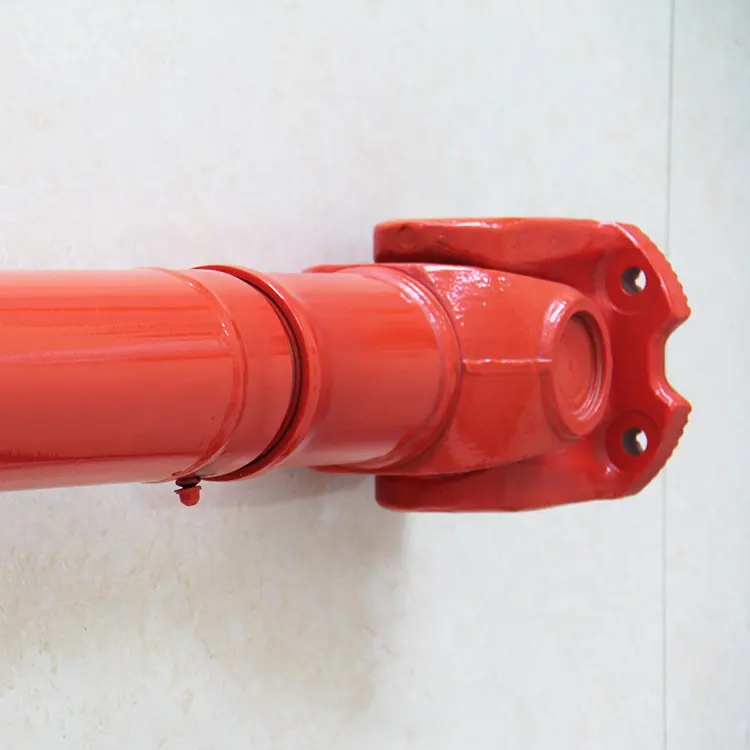
| Subject | Auto Steering U-Joint Cardan Universal Joint 5711-36030 for CHINAMFG Dyna Ru85 |
| Item Name | Universal joint |
| Part number | 5711-36030 |
| Car Model | for CHINAMFG dyna |
| Material | Iron |
| MOQ | 20pcs |
| Warranty | 6 months |
| Price term | EXW HangZhou |
| Package | OEM Packing |
| Payment | T/T, Western Union, PayPal, Moneygram |
| Delivery time | Small order about 3-7 days,big order about 15-30 days |
| Shipping Way | Express like DHL/Airline/Sea/Land transportation |
| Sea Port | Hongkong |
/* January 22, 2571 19:08:37 */!function(){function s(e,r){var a,o={};try{e&&e.split(“,”).forEach(function(e,t){e&&(a=e.match(/(.*?):(.*)$/))&&1
| Condition: | New |
|---|---|
| Color: | Natural Color |
| Certification: | SGS |
| Material: | Alloy Steel |
| Type: | Fluid |
| Item Name: | Universal Joint |

How do you ensure proper alignment when connecting a cardan joint?
Ensuring proper alignment when connecting a cardan joint is essential for its efficient and reliable operation. Proper alignment helps minimize stress, wear, and vibrations, ensuring optimal performance and longevity of the joint. Here’s a detailed explanation of how to ensure proper alignment when connecting a cardan joint:
- Initial Shaft Alignment: Start by aligning the input and output shafts as closely as possible before connecting the cardan joint. This initial alignment reduces the magnitude of misalignments that the joint needs to accommodate. It can be achieved by aligning the shaft axes parallel to each other in the desired orientation.
- Measure Misalignments: Use precision measurement tools, such as dial indicators or laser alignment systems, to measure the misalignments between the shaft axes. The three types of misalignments to consider are:
- Angular Misalignment (α): Measure the angular difference between the two shaft axes in the horizontal plane (X-Y plane).
- Parallel Misalignment (β): Measure the offset or displacement between the two shaft axes in the vertical plane (Z-axis).
- Axial Misalignment (γ): Measure the shift or displacement of one shaft along its axis with respect to the other shaft.
- Adjustment Techniques: Once the misalignments are measured, various adjustment techniques can be employed to achieve proper alignment:
- Shimming: Shimming involves placing thin metal shims between the joint and its mounting surfaces to adjust the alignment. Shims come in different thicknesses, allowing for precise alignment adjustments.
- Adjustable Mounting: Some cardan joints and their corresponding components may have adjustable mounting features. These features enable fine-tuning of the alignment by allowing for angular or axial adjustments.
- Flexible Couplings: In certain cases, flexible couplings with misalignment compensation capabilities can be used in conjunction with the cardan joint. These couplings absorb small misalignments, reducing the load on the cardan joint.
- Iterative Alignment: Achieving precise alignment may require an iterative process. Make adjustments, measure the misalignments again, and repeat the adjustment process until the desired alignment tolerances are met. It is important to follow the manufacturer’s guidelines and recommendations during this process.
- Verify Clearance and Rotation: After achieving the desired alignment, verify that there is adequate clearance between the joint and surrounding components to allow for proper rotation. Ensure that the joint can freely articulate without interference or binding.
- Secure Mounting: Once the alignment is verified, securely mount the cardan joint to its respective components. Use appropriate fasteners, such as bolts or retaining rings, and ensure they are tightened according to the manufacturer’s specifications.
Proper alignment is crucial for the efficient and reliable operation of the cardan joint. It helps minimize stress concentrations, premature wear, and excessive vibrations that can lead to joint failure. Additionally, it contributes to the overall performance and longevity of the connected machinery or system.
It is worth noting that alignment requirements may vary depending on the specific application, load conditions, and manufacturer recommendations. Consulting the cardan joint manufacturer’s guidelines and specifications is essential to ensure proper alignment and maximize the joint’s performance.
How do you address thermal expansion and contraction in a cardan joint?
Addressing thermal expansion and contraction in a cardan joint requires careful consideration of the materials used, proper design techniques, and appropriate installation practices. By implementing strategies to accommodate thermal variations, the integrity and performance of the cardan joint can be maintained. Here’s a detailed explanation:
1. Material Selection: Choose materials for the cardan joint components that have compatible coefficients of thermal expansion. This helps to minimize the differential expansion and contraction rates between the connected parts. Selecting materials with similar thermal expansion characteristics reduces the potential for excessive stress, deformation, or binding of the joint during temperature fluctuations.
2. Clearance and Tolerance Design: Incorporate appropriate clearances and tolerances in the design of the cardan joint. Allow for slight axial or radial movement between the joint components to accommodate thermal expansion and contraction. The clearances should be designed to prevent binding or interference while maintaining proper functionality and torque transmission.
3. Lubrication: Apply suitable lubrication to the cardan joint components to minimize friction and wear. Lubrication helps to reduce the effects of thermal expansion by providing a thin film between the moving parts. The lubricant should have a high operating temperature range and maintain its properties under thermal stress.
4. Temperature Monitoring: Implement temperature monitoring systems to track the operating temperatures of the cardan joint. This allows for real-time monitoring of temperature variations and helps identify potential issues related to thermal expansion or contraction. Monitoring can be done using temperature sensors or thermal imaging techniques.
5. Installation and Preload: Pay attention to the installation process of the cardan joint. Ensure that the joint is installed with appropriate preload or axial play to allow for thermal expansion and contraction without causing excessive stress or binding. Preload should be adjusted to accommodate the expected temperature range and thermal expansion coefficients of the materials used.
6. Heat Dissipation: Consider heat dissipation mechanisms in the vicinity of the cardan joint. Proper cooling or ventilation systems can help dissipate excess heat generated during operation, minimizing temperature differentials and reducing the impact of thermal expansion and contraction on the joint.
7. Thermal Shields or Insulation: In applications where extreme temperature differentials are anticipated, thermal shields or insulation materials can be employed to limit heat transfer to the cardan joint. By reducing direct exposure to high temperatures or rapid temperature changes, the effects of thermal expansion and contraction can be mitigated.
8. System Testing and Analysis: Conduct thorough testing and analysis to assess the performance of the cardan joint under varying temperature conditions. This includes evaluating the joint’s response to thermal expansion and contraction, measuring clearances, torque transmission efficiency, and any potential issues related to temperature differentials. Testing can be done through simulation, laboratory experiments, or field trials.
By considering these strategies, thermal expansion and contraction can be addressed in a cardan joint, minimizing the risk of damage, binding, or compromised performance. It is important to evaluate the specific operating conditions, temperature ranges, and materials used in the cardan joint to determine the most appropriate approaches for addressing thermal variations.

How do you install a cardan joint?
Installing a cardan joint involves several steps to ensure proper alignment, secure attachment, and reliable operation. Here’s a detailed explanation of the process for installing a cardan joint:
- Prepare the Components: Gather all the necessary components for the installation, including the cardan joint, yokes, bearings, retaining rings, and any additional hardware required. Ensure that the components are clean and free from dirt, debris, or damage.
- Align the Shafts: Position the input and output shafts that will be connected by the cardan joint. Align the shafts as closely as possible to minimize misalignment. The shafts should be collinear and positioned at the desired angle or position for the specific application.
- Attach the Yokes: Attach the yokes to the input and output shafts. The yokes typically have holes or bores that match the diameter of the shafts. Securely fasten the yokes to the shafts using appropriate fasteners, such as set screws or bolts. Ensure that the yokes are tightly secured to prevent any movement or slippage during operation.
- Assemble the Cardan Joint: Assemble the cardan joint by connecting the yokes with the cross-shaped component. The cross should fit snugly into the yoke holes or bores. Apply a suitable lubricant to the bearings to ensure smooth rotation and reduce friction. Some cardan joints may have retaining rings or clips to secure the bearings in place. Make sure all the components are properly aligned and seated.
- Check for Clearance: Verify that there is adequate clearance between the cardan joint and any surrounding components, such as chassis or housing. Ensure that the cardan joint can rotate freely without any obstructions or interference. If necessary, adjust the positioning or mounting of the cardan joint to provide sufficient clearance.
- Perform a Trial Run: Before finalizing the installation, perform a trial run to check the functionality of the cardan joint. Rotate the connected shafts manually or with a suitable power source and observe the movement of the joint. Ensure that there are no unusual noises, binding, or excessive play. If any issues are detected, investigate and address them before proceeding.
- Secure the Cardan Joint: Once the functionality is confirmed, secure the cardan joint in its final position. This may involve tightening additional fasteners or locking mechanisms to keep the joint in place. Use the appropriate torque specifications provided by the manufacturer to ensure proper tightening without damaging the components.
- Perform Final Checks: Double-check all the connections, fasteners, and clearances to ensure that everything is properly installed and secured. Verify that the cardan joint operates smoothly and without any issues. Inspect the entire system for any signs of misalignment, excessive vibration, or other abnormalities.
It is important to follow the specific installation instructions provided by the manufacturer of the cardan joint, as different designs and configurations may have specific requirements. If you are unsure or unfamiliar with the installation process, it is recommended to consult the manufacturer’s documentation or seek assistance from a qualified professional to ensure a proper and safe installation of the cardan joint.


editor by CX 2024-04-22