Product Description
|
Type |
Universal Joint |
|
Brand |
Huihai |
|
Car Model |
For CHINAMFG GMB NO. GUIS55 KOYO.NO. 14219A MATSUBA NO. UJ320 |
|
OE NO. |
9-37300-150 |
| Parameters |
27×81.75/20CR |
|
Condition |
100% new |
|
Warranty |
12 month |
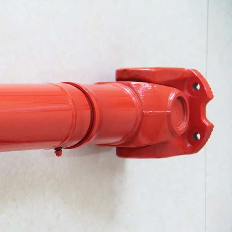
The Universal Joint is a part of variable Angle power transmission, which is used to change the direction of the transmission axis. It is the “joint” part of the universal transmission device of the automobile drive system. The combination of universal joint and transmission shaft is called universal joint transmission device. On the front-engine rear-wheel drive vehicle, the universal joint transmission device is installed between the transmission output shaft and the drive axle main reducer input shaft; The front-engine front-wheel drive vehicle omits the drive shaft, and the universal joint is installed between the front axle axle and the wheel, which is responsible for both driving and steering.
Q1.What is your MOQ?
A: We accept lower quantity for your trial order.
Q2. How long is the production lead time?
A: For some item we keep some stock that can be deliveried in 2 weeks.
Q3.What is your payment term?
A: Discussed! T/T / L/C /Paypal etc.
Q4.Can I customized my own Brand ?
A: Yes, we can do however you need to reach certain quantity for each item
Q5. What is a package?
A: Neutral packaging or customer packaging.
Q6. Can you help with the delivery of the goods?
A: Yes. We can help deliver goods through our customer freight forwarders or our freight forwarders.
Q7. Which port does our company supply?
A: Usually in HangZhou Port. The port specified by the customer is acceptable.
/* January 22, 2571 19:08:37 */!function(){function s(e,r){var a,o={};try{e&&e.split(“,”).forEach(function(e,t){e&&(a=e.match(/(.*?):(.*)$/))&&1
| After-sales Service: | One Year |
|---|---|
| Warranty: | One Year Warranty |
| Condition: | New |
| Color: | Silver |
| Certification: | ISO |
| Structure: | Single |

How do you prevent backlash and vibration issues in a cardan joint?
Preventing backlash and vibration issues in a cardan joint requires careful design considerations and proper maintenance. Here are some measures that can be taken to minimize backlash and vibration problems:
- High-Quality Manufacturing and Tolerances: Ensuring that the cardan joint is manufactured to high-quality standards and tight tolerances is crucial for minimizing backlash. Precision machining and assembly techniques can help reduce clearances and improve the overall fit of the joint components, resulting in reduced backlash.
- Proper Lubrication: Adequate lubrication is essential for reducing friction and minimizing backlash in a cardan joint. Lubricants with appropriate viscosity and properties should be used to ensure smooth operation and reduce wear. Regular maintenance, including lubricant replenishment or replacement as per the manufacturer’s recommendations, is necessary to maintain optimal lubrication and prevent backlash issues.
- Alignment and Balance: Proper alignment of the cardan joint and the connected components is critical for minimizing backlash and vibration. Misalignment can lead to uneven loading and increased stress on the joint, resulting in backlash and vibration. Ensuring precise alignment during installation and periodic checks for alignment deviations can help prevent these issues. Balancing the rotating components, such as the driveshaft, can also minimize vibration problems.
- Reducing Operating Angles: Operating the cardan joint within its specified angular limits can help minimize backlash and vibration. Exceeding the recommended operating angles can cause increased misalignment, leading to higher levels of backlash and vibration. If large operating angles are necessary, a constant velocity joint or alternative coupling mechanism may be considered to achieve smoother motion and reduced backlash.
- Regular Maintenance and Inspection: Performing regular maintenance and inspections on the cardan joint is crucial for preventing backlash and vibration issues. This includes checking for wear, proper lubrication, alignment deviations, and any signs of damage or fatigue. Any detected issues should be promptly addressed to prevent further deterioration and ensure the optimal performance of the joint.
- Vibration Dampening: In some cases, additional measures can be taken to dampen vibrations in the system. This can include the use of vibration-dampening materials or techniques, such as rubber bushings or vibration isolators, at the connection points of the cardan joint. These measures can help absorb and dampen vibrations, reducing their impact on the joint and the connected components.
By implementing these preventive measures, the potential backlash and vibration issues in a cardan joint can be minimized. It is important to consider the specific requirements of the application and follow the manufacturer’s guidelines for installation, maintenance, and operation to ensure the optimal performance and longevity of the joint.
How do you address thermal expansion and contraction in a cardan joint?
Addressing thermal expansion and contraction in a cardan joint requires careful consideration of the materials used, proper design techniques, and appropriate installation practices. By implementing strategies to accommodate thermal variations, the integrity and performance of the cardan joint can be maintained. Here’s a detailed explanation:
1. Material Selection: Choose materials for the cardan joint components that have compatible coefficients of thermal expansion. This helps to minimize the differential expansion and contraction rates between the connected parts. Selecting materials with similar thermal expansion characteristics reduces the potential for excessive stress, deformation, or binding of the joint during temperature fluctuations.
2. Clearance and Tolerance Design: Incorporate appropriate clearances and tolerances in the design of the cardan joint. Allow for slight axial or radial movement between the joint components to accommodate thermal expansion and contraction. The clearances should be designed to prevent binding or interference while maintaining proper functionality and torque transmission.
3. Lubrication: Apply suitable lubrication to the cardan joint components to minimize friction and wear. Lubrication helps to reduce the effects of thermal expansion by providing a thin film between the moving parts. The lubricant should have a high operating temperature range and maintain its properties under thermal stress.
4. Temperature Monitoring: Implement temperature monitoring systems to track the operating temperatures of the cardan joint. This allows for real-time monitoring of temperature variations and helps identify potential issues related to thermal expansion or contraction. Monitoring can be done using temperature sensors or thermal imaging techniques.
5. Installation and Preload: Pay attention to the installation process of the cardan joint. Ensure that the joint is installed with appropriate preload or axial play to allow for thermal expansion and contraction without causing excessive stress or binding. Preload should be adjusted to accommodate the expected temperature range and thermal expansion coefficients of the materials used.
6. Heat Dissipation: Consider heat dissipation mechanisms in the vicinity of the cardan joint. Proper cooling or ventilation systems can help dissipate excess heat generated during operation, minimizing temperature differentials and reducing the impact of thermal expansion and contraction on the joint.
7. Thermal Shields or Insulation: In applications where extreme temperature differentials are anticipated, thermal shields or insulation materials can be employed to limit heat transfer to the cardan joint. By reducing direct exposure to high temperatures or rapid temperature changes, the effects of thermal expansion and contraction can be mitigated.
8. System Testing and Analysis: Conduct thorough testing and analysis to assess the performance of the cardan joint under varying temperature conditions. This includes evaluating the joint’s response to thermal expansion and contraction, measuring clearances, torque transmission efficiency, and any potential issues related to temperature differentials. Testing can be done through simulation, laboratory experiments, or field trials.
By considering these strategies, thermal expansion and contraction can be addressed in a cardan joint, minimizing the risk of damage, binding, or compromised performance. It is important to evaluate the specific operating conditions, temperature ranges, and materials used in the cardan joint to determine the most appropriate approaches for addressing thermal variations.

How do you maintain and service a cardan joint?
Maintaining and servicing a cardan joint is important to ensure its optimal performance, reliability, and longevity. Regular maintenance helps prevent premature wear, address potential issues, and prolong the life of the joint. Here’s a detailed explanation of the maintenance and servicing procedures for a cardan joint:
- Visual Inspection: Regularly inspect the cardan joint for any visible signs of damage, wear, or misalignment. Look for cracks, corrosion, loose or missing fasteners, worn bearings, or any abnormalities in the joint components. If any issues are identified, they should be addressed promptly.
- Lubrication: Proper lubrication is essential for the smooth operation of a cardan joint. Follow the manufacturer’s recommendations regarding lubrication type, frequency, quantity, and method. Regularly apply the appropriate lubricant to the designated lubrication points or zerk fittings. Monitor the condition of the lubricant and replenish it as needed to maintain optimal lubrication levels.
- Torque Check: Periodically check the torque of the fasteners that secure the cardan joint and yokes. Over time, vibration and operational stresses can cause fasteners to loosen. Ensure that all fasteners are tightened to the manufacturer’s specified torque values. Be cautious not to overtighten, as it can lead to component damage or failure.
- Alignment Verification: Verify the alignment of the connected shafts that are linked by the cardan joint. Misalignment can cause increased stress and wear on the joint components. Check for any angular misalignment or axial misalignment and make necessary adjustments to minimize misalignment within acceptable tolerances.
- Load and Operating Condition Evaluation: Regularly evaluate the load and operating conditions in which the cardan joint operates. Ensure that the joint is not subjected to excessive loads, speeds, or harsh operating environments beyond its design capabilities. If there are any changes in the operating conditions, consider consulting the manufacturer or an expert to assess the suitability of the cardan joint and make any necessary modifications or replacements.
- Vibration Monitoring: Monitor the vibration levels during operation, as excessive vibration can indicate issues with the cardan joint or the overall system. An increase in vibration may suggest misalignment, worn bearings, or other mechanical problems. If significant vibration is detected, further investigation and corrective actions should be undertaken to address the root cause.
- Periodic Disassembly and Inspection: Depending on the manufacturer’s recommendations and the operating conditions, periodic disassembly and inspection of the cardan joint may be required. This allows for a more thorough assessment of the joint’s condition, including the bearings, seals, and other internal components. Any worn or damaged parts should be replaced with genuine manufacturer-approved replacements.
- Professional Maintenance: In some cases, it may be necessary to engage the services of a professional maintenance technician or a specialized service provider for more comprehensive maintenance or servicing of the cardan joint. They can perform advanced inspections, alignment checks, bearing replacements, or other specialized procedures to ensure the optimal performance of the joint.
It is important to follow the manufacturer’s guidelines and recommendations for maintenance and servicing of the specific cardan joint model. Adhering to proper maintenance practices and promptly addressing any issues that arise will help maximize the service life, reliability, and performance of the cardan joint.


editor by CX 2024-04-13
China Best Sales 2023 SA8t/K Sal8t/K M8X1.25 Fisheye Rod End Joint Bearing Universal Joint, Self-Lubricating Male Thread
Product Description
SA…PK Series Rod Ends is same as NOS Series Rod Ends,they are belong to maintenance-free Rod Ends bearing. The rod end body is equipped with a left-hand or right-hand external thread. The rod end body is formed by extrusion and the surface of the rod end body is galvanized. And The outer sphere is lined with PTFE synthetic material.
Company Profile
Yiboyuan (HangZhou City) Precision Machinery Co., Ltd. is located in Bacha Road Industrial Park, HangZhou City, HangZhou City, ZheJiang Province, is a professional manufacturer of linear bearings
integrating design, research and development, production and sales. The company’s main products are: YBYZ linear bearings, YBYZ linear flange bearings, YBYZ nickel-plated linear bearings, YBYZ steel linear bearings, YBYZ box sliders, YBYZ smooth shaft supports, YBYZ self lubricating bearings, YBYZ outer steel inner copper linear bearings, YBYZ aluminum-plastic linear bearings, YBYZ all-plastic linear
bearings, YBYZ graphite copper sleeved linear bearings, YBYZ fixed rings, nut seats, cross shaft brackets and so on. Yiboyuan linear bearings should build the most complete linear bearing enterprises and smooth shaft supporting products at home and abroad, and solve one-stop procurement services for automation companies.Our mission – to create revenue benefits for customers, provide high-quality products for the market, and create a stage for employees to play, the future Yiboyuan is a high-tech, service-oriented, international Yiboyuan, to build a century-old brand is our continuous goal.
Brand trademark registration
Yiboyuan (HangZhou) Precision Machinery Co., Ltd. is a professional manufacturer of linear motion products with many years of experience. And has its own registered brand YBYZ, we specialize in the production of linear bearings, plain bearings, shaft bearings, box sliders, self-lubricating copper sleeve. Good quality, competitive price. Our company is located in HangZhou City, ZheJiang Province. Close to HangZhou Port, ZheJiang Port.
Our products are widely used in precision machinery, fitness equipment, printing presses, packaging machines, medical and food machinery, textile machinery and other machinery and auxiliary equipment. Our products sell well in North America, Western Europe, Australia, Southeast Asia, the Middle East, South America and other regions.
Our packing:
* Industrial pakage
HangZhou City, ZheJiang Province.
/* March 10, 2571 17:59:20 */!function(){function s(e,r){var a,o={};try{e&&e.split(“,”).forEach(function(e,t){e&&(a=e.match(/(.*?):(.*)$/))&&1
| Rolling Element: | Single Row |
|---|---|
| Structure: | Rod End |
| Material: | Bearing Steel |
| Load Direction: | Radial Spherical Plain Bearing |
| Add Lubricant: | Self-lubricating |
| Outer Structure: | Whole Outer Ring |
| Samples: |
US$ 0.1/Piece
1 Piece(Min.Order) | |
|---|
| Customization: |
Available
| Customized Request |
|---|

What are the safety considerations when working with universal joints?
Working with universal joints requires adherence to certain safety considerations to prevent accidents, injuries, and equipment damage. Here’s a detailed explanation:
When dealing with universal joints, it is important to keep the following safety considerations in mind:
- Proper Training and Knowledge: Ensure that individuals working with universal joints have the necessary training and knowledge of their operation, installation, and maintenance. Familiarity with safety procedures and understanding the potential hazards associated with universal joints is crucial for safe handling.
- Personal Protective Equipment (PPE): Use appropriate personal protective equipment, such as safety glasses, gloves, and protective clothing, when working with universal joints. PPE can provide protection against potential hazards, including sharp edges, pinch points, or flying debris during installation, removal, or maintenance activities.
- Secure the System: Before working on a system that involves universal joints, ensure that the equipment is securely shut down and de-energized. Lockout/tagout procedures should be followed to prevent unexpected energization or movement that could cause injury. Securely support any components or shafts connected to the universal joint to prevent accidental movement or collapse during work.
- Inspect for Damage or Wear: Regularly inspect universal joints for signs of damage, wear, or misalignment. Look for indications of excessive play, corrosion, fatigue, or any other abnormalities that may compromise the joint’s integrity. Replace any worn or damaged components promptly to avoid potential failure during operation.
- Safe Handling: When installing or removing universal joints, use proper lifting techniques and equipment to avoid strain or injury. Universal joints can be heavy and cumbersome, so mechanical assistance or lifting devices may be necessary. Follow safe handling practices and avoid placing hands or body parts in the path of rotating or moving components.
- Avoid Exceeding Design Limits: Universal joints have specific design limits for torque, operating angles, and speed. Ensure that these limits are not exceeded during operation. Exceeding the design limits can lead to premature wear, distortion, or catastrophic failure of the joint. Always consult the manufacturer’s guidelines and specifications to ensure safe operation within the defined limits.
- Lubrication and Maintenance: Proper lubrication is essential for the smooth operation and longevity of universal joints. Follow the manufacturer’s recommendations for lubrication intervals and use the specified lubricants. Regularly inspect and maintain the joint, tightening fasteners as needed and addressing any signs of lubrication breakdown, contamination, or leakage.
- Appropriate Tools and Equipment: Use the correct tools and equipment for working with universal joints. Improper tools or techniques can cause damage to the joint or result in injuries. Ensure that tools are in good condition, properly calibrated, and suitable for the specific task at hand.
- Follow Manufacturer Guidelines: Always follow the manufacturer’s guidelines, instructions, and safety precautions specific to the universal joint being used. Manufacturers provide important information regarding installation, operation, maintenance, and safety considerations that should be strictly adhered to.
By adhering to these safety considerations, individuals can minimize the risk of accidents, injuries, and equipment damage when working with universal joints.

What materials are commonly used in the construction of universal joints?
Universal joints are constructed using various materials that provide strength, durability, and resistance to wear and fatigue. Here’s a detailed explanation:
The choice of materials for universal joints depends on factors such as the application, load requirements, operating conditions, and cost considerations. Here are some commonly used materials:
- Steel: Steel is one of the most common materials used in universal joint construction. Alloy steels, such as 4140 or 4340, are often employed due to their high strength, toughness, and resistance to wear and fatigue. Steel universal joints can withstand heavy loads and harsh operating conditions, making them suitable for various industrial applications.
- Stainless Steel: Stainless steel is chosen for universal joints when corrosion resistance is a critical requirement. Stainless steel alloys, such as 304 or 316, offer excellent resistance to rust, oxidation, and chemical corrosion. These joints are commonly used in applications where exposure to moisture, chemicals, or harsh environments is expected.
- Cast Iron: Cast iron is occasionally used in universal joints, particularly in older or specialized applications. Cast iron provides good strength and wear resistance, but it is generally heavier and less flexible than steel. It may be used in specific situations where its properties are advantageous, such as in large industrial machinery.
- Aluminum: Aluminum universal joints are utilized when weight reduction is a priority. Aluminum alloys offer a good balance of strength and lightweight properties. These joints are commonly found in applications where weight savings are crucial, such as aerospace, automotive, or robotics.
- Bronze: Bronze is sometimes used for bearings or bushings within universal joints. Bronze alloys provide good wear resistance, low friction, and the ability to withstand high temperatures. They are often employed in applications where self-lubricating properties and resistance to galling are required. Bronze bearings can be found in universal joints used in heavy machinery, marine equipment, or agricultural machinery.
It’s worth noting that the specific choice of materials may vary depending on the manufacturer, application requirements, and industry standards. Different combinations of materials may also be used for different components within a universal joint, such as the yokes, crosses, bearings, or seals, to optimize performance and durability.
In summary, universal joints are commonly constructed using materials such as steel, stainless steel, cast iron, aluminum, and bronze. The selection of materials depends on factors like strength, durability, wear resistance, corrosion resistance, weight considerations, and specific application requirements.

What industries commonly use universal joints?
Universal joints, also known as U-joints, are utilized in various industries where the transmission of rotary motion between misaligned shafts is required. Here are some of the industries that commonly use universal joints:
- Automotive: The automotive industry extensively employs universal joints in vehicles. Universal joints are essential components in drivelines, connecting the transmission to the drive shaft and allowing power to be transmitted to the wheels. They accommodate the misalignment caused by the suspension system and enable smooth power transfer.
- Industrial Manufacturing: Universal joints find widespread use in industrial manufacturing applications. They are employed in machinery and equipment such as conveyors, mixers, pumps, printing presses, and machine tools. Universal joints facilitate the transmission of motion at angles, enabling efficient operation and flexibility in various manufacturing processes.
- Aerospace: The aerospace industry utilizes universal joints in aircraft and spacecraft systems. They are used in control mechanisms for movable surfaces such as wings, flaps, and rudders. Universal joints enable the transfer of motion and control inputs between different components, ensuring precise and reliable operation of aerospace systems.
- Marine: Universal joints are commonly employed in the marine industry for various applications. They are used in propulsion systems to transmit power from the engine to the propeller shaft. Universal joints also find application in steering systems, allowing for the transfer of motion between the steering wheel and the rudder or outboard motor.
- Agriculture: The agricultural industry relies on universal joints in various machinery and equipment used in farming operations. Tractors, combines, harvesters, and other agricultural machinery utilize universal joints to transmit power between different components, accommodating misalignment caused by the terrain and articulation requirements.
- Construction and Heavy Equipment: Universal joints are commonly found in construction and heavy equipment. They are used in machinery such as cranes, excavators, loaders, and concrete mixers. Universal joints enable the transmission of power and motion between different parts of the equipment, accommodating misalignment and articulation required in construction and heavy-duty operations.
- Railway: The railway industry relies on universal joints for various applications. They are used in drivetrain systems to transmit motion between different components, such as the engine, gearbox, and axles. Universal joints allow for smooth power transfer while accommodating the misalignment caused by the movement and suspension of trains.
- Robotics and Automation: Universal joints are utilized in robotics and automation systems. They enable the transmission of motion between misaligned components in robotic arms, manipulators, and other automated systems. Universal joints provide flexibility and precise movement, allowing for efficient operation of robotic and automated processes.
These are just a few examples of the industries that commonly use universal joints. Their ability to transmit rotary motion between misaligned shafts makes them essential components in a wide range of applications, enabling efficient and reliable operation across various industries.
editor by CX 2024-02-06
China Best Sales Truck Parts 22X55 U-Joints Bearing Universal Joints Crucetas Joints De Cardan Cross
Product Description
Product Description
Universal Coupling Cross Bearing Automobile Bearing Universal Joint Bearing
FAQ
1.Q: How do you pack the bearing ?
A: It is ORIGINAL packaging.
It can be done as your specfic demands.
2.Q: Can I get some samples and do you offer the sample free?
A: Yes, sure, we are honored to offer you samples.If we have stock, we can send you free sample.
And you just need to pay freight. If there have no stock, you need to pay sample fee and freight.
3.Q: Does the sample fee can be return back?
A: If you place an order, we can return part of sample fee even all of fee to you.It also depends
on the Quantity of order and the type of sample.
4.Q: What is the MOQ for bearing?
A: Our MOQ is 1 pc.
5.Q: What is the delivery time?
A: According to the order amount or as your request.
6.Q: Can you promise to deliver bearing CHINAMFG 3530 in time?
A: Credit always ranks the top on the list. We will absolutely deliver the goods in 2-4 days after your order is confirmed.
| Aligning: | Non-Aligning Bearing |
|---|---|
| Separated: | Separated |
| Material: | Bearing Steel |
| Samples: |
US$ 5/Piece
1 Piece(Min.Order) | Order Sample |
|---|
| Customization: |
Available
| Customized Request |
|---|
.shipping-cost-tm .tm-status-off{background: none;padding:0;color: #1470cc}
|
Shipping Cost:
Estimated freight per unit. |
about shipping cost and estimated delivery time. |
|---|
| Payment Method: |
|
|---|---|
|
Initial Payment Full Payment |
| Currency: | US$ |
|---|
| Return&refunds: | You can apply for a refund up to 30 days after receipt of the products. |
|---|

Are cardan joints suitable for both high-torque and high-speed applications?
Cardan joints can be used in a variety of applications, but their suitability for high-torque and high-speed applications depends on several factors. Here’s a detailed explanation of the considerations regarding the use of cardan joints in such scenarios:
1. High-Torque Applications: Cardan joints are generally well-suited for high-torque applications. The design of the joint allows for the transmission of significant torque between misaligned shafts. However, it is important to consider the specific torque requirements and operating conditions. Factors such as the size and type of the joint, the material used, and the application’s torque demands should be taken into account. In extremely high-torque applications, alternative coupling mechanisms such as gear couplings or universal joints may be more appropriate.
2. High-Speed Applications: While cardan joints can operate at relatively high speeds, there are some limitations to consider. At high rotational speeds, cardan joints can experience increased vibration, imbalance, and potential for fatigue failure. The rotating components of the joint can generate centrifugal forces, which can impact the balance and stability of the system. To mitigate these issues, careful design considerations, including balancing and vibration analysis, may be necessary. In some cases, alternative coupling mechanisms like flexible couplings or constant velocity joints may be better suited for high-speed applications.
3. Balancing and Vibration Control: Balancing the rotating components, such as the driveshaft and the joint itself, is essential for minimizing vibration issues in high-torque and high-speed applications. Imbalance can lead to increased vibrations, reduced efficiency, and potential damage to the joint and other system components. Proper balancing techniques, including dynamic balancing during manufacturing or precision balancing during installation, can help achieve smoother operation and minimize vibration problems.
4. Material Selection: The material used in the construction of the cardan joint plays a crucial role in its suitability for high-torque and high-speed applications. High-strength materials, such as alloy steels, are often preferred for their ability to handle increased torque loads. Additionally, materials with good fatigue resistance and high-speed capabilities can help ensure the durability and reliability of the joint in demanding applications.
5. Application-Specific Factors: The suitability of cardan joints for high-torque and high-speed applications also depends on the specific requirements and operating conditions of the application. Factors such as load characteristics, duty cycles, temperature, and environmental conditions should be considered. It is important to consult with the manufacturer or engineering experts to determine the appropriate size, type, and configuration of the cardan joint for a particular high-torque or high-speed application.
In summary, cardan joints can be suitable for both high-torque and high-speed applications, but careful consideration of factors such as torque requirements, speed limitations, balancing, material selection, and application-specific conditions is necessary. Evaluating these factors and consulting with experts can help determine the optimal coupling solution for a given high-torque or high-speed application.

Can cardan joints be used in pumps and compressors?
Yes, cardan joints can be used in pumps and compressors to transmit torque and accommodate misalignments between the driving and driven shafts. They offer several advantages that make them suitable for these applications. Here’s a detailed explanation:
1. Torque Transmission: Pumps and compressors often require the transmission of torque from the driving motor or engine to the rotating shaft that operates the pump or compressor. Cardan joints excel at transmitting torque efficiently, even at significant angles and misalignments. They can handle the high torque loads typically encountered in pump and compressor applications.
2. Misalignment Compensation: Cardan joints are designed to accommodate misalignments between the driving and driven shafts. In pumps and compressors, misalignments can occur due to factors such as thermal expansion, structural deflection, or assembly tolerances. Cardan joints can compensate for these misalignments, ensuring smooth and reliable torque transmission without excessive stress or wear on the connected components.
3. Angular Flexibility: Pumps and compressors often require flexibility in their drivetrain to adapt to different installation configurations or accommodate dynamic movements. Cardan joints provide rotational freedom and allow for angular movement, enabling the pump or compressor to adjust to changing requirements. Their universal joint design allows for smooth rotation and accommodates the required range of motion.
4. Shock and Vibration Absorption: Pumps and compressors can generate significant vibrations and shocks during operation. Cardan joints help absorb these vibrations and shocks, reducing their transmission to the rest of the drivetrain. This feature helps protect other components, such as bearings and seals, from excessive stress and wear, enhancing the overall reliability and lifespan of the pump or compressor.
5. Compact Design: Cardan joints have a relatively compact design, making them suitable for integration into pump and compressor systems where space is often limited. Their compact size allows for efficient packaging within the equipment, optimizing overall design and minimizing footprint. This is especially beneficial in applications where multiple joints are required within a confined space.
6. Durability and Strength: Pumps and compressors operate under demanding conditions, including high pressures, heavy loads, and continuous operation. Cardan joints are often constructed using durable materials such as alloy steels or high-strength alloys, providing the necessary strength and resilience to withstand these conditions. They are designed to handle the demanding loads and forces encountered in pump and compressor applications.
7. Easy Maintenance and Serviceability: Cardan joints are generally low-maintenance components. They require periodic inspection, lubrication, and replacement of worn parts, but their design often allows for easy access and replacement if needed. This facilitates maintenance activities and minimizes downtime in pump and compressor systems.
8. Cost-Effectiveness: Cardan joints offer a cost-effective solution for torque transmission in pump and compressor applications. Their durability, reliability, and long service life contribute to reduced maintenance and replacement costs. Additionally, their ability to accommodate misalignments helps minimize wear on other drivetrain components, further reducing overall maintenance expenses.
When integrating cardan joints into pump and compressor systems, it is important to consider the specific application requirements, operating conditions, and load characteristics. Proper design, selection, and installation practices should be followed to ensure optimal performance and longevity.
Consulting with engineers or experts specializing in drivetrain systems and pump/compressor design can provide valuable insights and guidance on the selection, integration, and maintenance of cardan joints for these applications.
Can you provide examples of vehicles that use cardan joints?
Cardan joints, also known as universal joints, are commonly used in various vehicles to transmit rotational motion between two shafts that are not in perfect alignment. Here are some examples of vehicles that utilize cardan joints:
- Automobiles: Cardan joints are widely employed in automobiles for various applications. They are commonly found in the drivetrain system, connecting the transmission output shaft to the driveshaft. This allows the rotational power to be transferred from the engine to the wheels, enabling the vehicle to move. Cardan joints are also used in the steering system to transmit motion from the steering column to the steering rack or gearbox.
- Trucks and Commercial Vehicles: Cardan joints are extensively used in trucks and commercial vehicles for their drivetrain and suspension systems. They are often employed in the propeller shafts to transmit power from the transmission or transfer case to the rear axle or multiple axles in the case of multi-axle trucks. Cardan joints are also utilized in the steering linkage system of heavy-duty trucks and buses.
- Off-Road and 4×4 Vehicles: Off-road vehicles and 4×4 vehicles heavily rely on cardan joints for their drivetrain systems. These joints are used in the transfer case to transmit power to both the front and rear differentials, enabling selectable four-wheel drive or all-wheel drive capabilities. Cardan joints provide flexibility to accommodate the articulation and suspension movement required in off-road conditions.
- Agricultural Machinery: Cardan joints are commonly employed in agricultural machinery, such as tractors and combines. They are utilized in the power take-off (PTO) shafts to transfer rotational power from the engine to various implements and attachments, such as mowers, balers, or harvesters. Cardan joints allow for the smooth transfer of power while accommodating the movement and positioning of the implements.
- Railway Locomotives and Rolling Stock: Cardan joints are utilized in the drivetrain systems of railway locomotives and rolling stock. They are used in the propeller shafts to transmit power from the engine or motor to the wheels. Cardan joints allow for the required flexibility and compensation of misalignment between the various components of the drivetrain system.
- Industrial Machinery and Equipment: Cardan joints find applications in various industrial machinery and equipment. They are used in industrial drive systems, such as conveyors, pumps, generators, and heavy-duty machinery. Cardan joints enable the transmission of rotational power between different components or sections of the machinery while accommodating misalignment and angular variations.
These are just a few examples of vehicles and applications where cardan joints are commonly used. The versatility, flexibility, and reliability of cardan joints make them suitable for a wide range of vehicles and machinery that require the transmission of rotational motion between non-aligned shafts.
editor by CX 2023-11-09
China Professional Wheeled Loader Spare Parts Bearing 150212K Bearing Housing Types Stainless Steel Square Fixed Seat Pillow Block Bearing with Housing Square Bear Fabrica Price with Best Sales
Product Description
Dear friends!
My name is Irina Mamoshina. Please pay a moment of your attention : -).
Our company HangZhou CZPT International Trade Co., Ltd is engaged in the production and sale of auto parts for Chinese special equipment, engines and equipment assembly. We also produce metal parts ourselves, such as gears, fingers, filters, etc.
Our products include:
ZL30G, ZL40G, ZL50G, ZL50GL, ZL60G, LW3
What Are Screw Shaft Threads?
A screw shaft is a threaded part used to fasten other components. The threads on a screw shaft are often described by their Coefficient of Friction, which describes how much friction is present between the mating surfaces. This article discusses these characteristics as well as the Material and Helix angle. You’ll have a better understanding of your screw shaft’s threads after reading this article. Here are some examples. Once you understand these details, you’ll be able to select the best screw nut for your needs.
Coefficient of friction between the mating surfaces of a nut and a screw shaft
There are 2 types of friction coefficients. Dynamic friction and static friction. The latter refers to the amount of friction a nut has to resist an opposing motion. In addition to the material strength, a higher coefficient of friction can cause stick-slip. This can lead to intermittent running behavior and loud squeaking. Stick-slip may lead to a malfunctioning plain bearing. Rough shafts can be used to improve this condition.
The 2 types of friction coefficients are related to the applied force. When applying force, the applied force must equal the nut’s pitch diameter. When the screw shaft is tightened, the force may be removed. In the case of a loosening clamp, the applied force is smaller than the bolt’s pitch diameter. Therefore, the higher the property class of the bolt, the lower the coefficient of friction.
In most cases, the screwface coefficient of friction is lower than the nut face. This is because of zinc plating on the joint surface. Moreover, power screws are commonly used in the aerospace industry. Whether or not they are power screws, they are typically made of carbon steel, alloy steel, or stainless steel. They are often used in conjunction with bronze or plastic nuts, which are preferred in higher-duty applications. These screws often require no holding brakes and are extremely easy to use in many applications.
The coefficient of friction between the mating surfaces of t-screws is highly dependent on the material of the screw and the nut. For example, screws with internal lubricated plastic nuts use bearing-grade bronze nuts. These nuts are usually used on carbon steel screws, but can be used with stainless steel screws. In addition to this, they are easy to clean.
Helix angle
In most applications, the helix angle of a screw shaft is an important factor for torque calculation. There are 2 types of helix angle: right and left hand. The right hand screw is usually smaller than the left hand one. The left hand screw is larger than the right hand screw. However, there are some exceptions to the rule. A left hand screw may have a greater helix angle than a right hand screw.
A screw’s helix angle is the angle formed by the helix and the axial line. Although the helix angle is not usually changed, it can have a significant effect on the processing of the screw and the amount of material conveyed. These changes are more common in 2 stage and special mixing screws, and metering screws. These measurements are crucial for determining the helix angle. In most cases, the lead angle is the correct angle when the screw shaft has the right helix angle.
High helix screws have large leads, sometimes up to 6 times the screw diameter. These screws reduce the screw diameter, mass, and inertia, allowing for higher speed and precision. High helix screws are also low-rotation, so they minimize vibrations and audible noises. But the right helix angle is important in any application. You must carefully choose the right type of screw for the job at hand.
If you choose a screw gear that has a helix angle other than parallel, you should select a thrust bearing with a correspondingly large center distance. In the case of a screw gear, a 45-degree helix angle is most common. A helix angle greater than zero degrees is also acceptable. Mixing up helix angles is beneficial because it allows for a variety of center distances and unique applications.
Thread angle
The thread angle of a screw shaft is measured from the base of the head of the screw to the top of the screw’s thread. In America, the standard screw thread angle is 60 degrees. The standard thread angle was not widely adopted until the early twentieth century. A committee was established by the Franklin Institute in 1864 to study screw threads. The committee recommended the Sellers thread, which was modified into the United States Standard Thread. The standardized thread was adopted by the United States Navy in 1868 and was recommended for construction by the Master Car Builders’ Association in 1871.
Generally speaking, the major diameter of a screw’s threads is the outside diameter. The major diameter of a nut is not directly measured, but can be determined with go/no-go gauges. It is necessary to understand the major and minor diameters in relation to each other in order to determine a screw’s thread angle. Once this is known, the next step is to determine how much of a pitch is necessary to ensure a screw’s proper function.
Helix angle and thread angle are 2 different types of angles that affect screw efficiency. For a lead screw, the helix angle is the angle between the helix of the thread and the line perpendicular to the axis of rotation. A lead screw has a greater helix angle than a helical one, but has higher frictional losses. A high-quality lead screw requires a higher torque to rotate. Thread angle and lead angle are complementary angles, but each screw has its own specific advantages.
Screw pitch and TPI have little to do with tolerances, craftsmanship, quality, or cost, but rather the size of a screw’s thread relative to its diameter. Compared to a standard screw, the fine and coarse threads are easier to tighten. The coarser thread is deeper, which results in lower torques. If a screw fails because of torsional shear, it is likely to be a result of a small minor diameter.
Material
Screws have a variety of different sizes, shapes, and materials. They are typically machined on CNC machines and lathes. Each type is used for different purposes. The size and material of a screw shaft are influenced by how it will be used. The following sections give an overview of the main types of screw shafts. Each 1 is designed to perform a specific function. If you have questions about a specific type, contact your local machine shop.
Lead screws are cheaper than ball screws and are used in light-duty, intermittent applications. Lead screws, however, have poor efficiency and are not recommended for continuous power transmission. But, they are effective in vertical applications and are more compact. Lead screws are typically used as a kinematic pair with a ball screw. Some types of lead screws also have self-locking properties. Because they have a low coefficient of friction, they have a compact design and very few parts.
Screws are made of a variety of metals and alloys. Steel is an economical and durable material, but there are also alloy steel and stainless steel types. Bronze nuts are the most common and are often used in higher-duty applications. Plastic nuts provide low-friction, which helps reduce the drive torques. Stainless steel screws are also used in high-performance applications, and may be made of titanium. The materials used to create screw shafts vary, but they all have their specific functions.
Screws are used in a wide range of applications, from industrial and consumer products to transportation equipment. They are used in many different industries, and the materials they’re made of can determine their life. The life of a screw depends on the load that it bears, the design of its internal structure, lubrication, and machining processes. When choosing screw assemblies, look for a screw made from the highest quality steels possible. Usually, the materials are very clean, so they’re a great choice for a screw. However, the presence of imperfections may cause a normal fatigue failure.
Self-locking features
Screws are known to be self-locking by nature. The mechanism for this feature is based on several factors, such as the pitch angle of the threads, material pairing, lubrication, and heating. This feature is only possible if the shaft is subjected to conditions that are not likely to cause the threads to loosen on their own. The self-locking ability of a screw depends on several factors, including the pitch angle of the thread flank and the coefficient of sliding friction between the 2 materials.
One of the most common uses of screws is in a screw top container lid, corkscrew, threaded pipe joint, vise, C-clamp, and screw jack. Other applications of screw shafts include transferring power, but these are often intermittent and low-power operations. Screws are also used to move material in Archimedes’ screw, auger earth drill, screw conveyor, and micrometer.
A common self-locking feature for a screw is the presence of a lead screw. A screw with a low PV value is safe to operate, but a screw with high PV will need a lower rotation speed. Another example is a self-locking screw that does not require lubrication. The PV value is also dependent on the material of the screw’s construction, as well as its lubrication conditions. Finally, a screw’s end fixity – the way the screw is supported – affects the performance and efficiency of a screw.
Lead screws are less expensive and easier to manufacture. They are a good choice for light-weight and intermittent applications. These screws also have self-locking capabilities. They can be self-tightened and require less torque for driving than other types. The advantage of lead screws is their small size and minimal number of parts. They are highly efficient in vertical and intermittent applications. They are not as accurate as lead screws and often have backlash, which is caused by insufficient threads.


China best Automobile Universal Joint Bearing Cross Bearing Wholesale, Sales Promotion near me supplier
Product Description
Products introduction
Universal joints cross bearing
Features:
1, Material: C45(1045) carbon steel, 40Cr steel, 20CrMnTi
2, Excellent performance, long service life and competitive price.
3, Great intensity and rigidity.
4, On time delivery
5, Own ISO9
Quality Assurance Document:
All the Q. A Document as per Client Requirement will be submitted when goods ready.
Packing and Shipping
1. Standard: Wooden case or carton for export
2. Delivery: As per contract delivery on time
3. Shipping: As per client request. We can accept CIF, Door to Door etc. Or client authorized agent we supply all the necessary assistant
Our service:
1. Customized and designed according to the customers’ sample, drawing or requirements
2. Following the customers’ requirements or as our usual packing
3. High quality and competitive price and pure-hearted service.
4. Strictly quality control according to ISO9001: 2008.
5. Flexible minimum order quantity
Our universal joints are with good quality and reasonable price. We can supply you all kinds of u-joints for more than 20 brands’ cars, mechanic machines and agriculture machines.
We can also supply universal joint, heavy duty universal joint, CZPT universal joint, gmb universal joints, small universal joint shaft, universal joint bearing, agriculture universal joints, small universal joints, universal joint yoke, universal joint coupling, universal joint spider, tractor universal joint, universal joint, universal joints cross bearing, plastic universal joint, universal joint cross, universal joint for cars, universal joint shaft, industrial universal joint, universal joint connector, universal joint, universal joint impact sockets, steering universal joint, universal joint pin, etc.
1.Q:Are you a factory or trading company?
A: Bearing is specialized in manufacturing and exporting bearings.
Bearing have own factory and warehouse.
2.Q:Can I get some samples and do you offer the sample free?
A:Yes, sure, Bearing are honored to offer you samples.Can you buy a ticket ?
3.Q:What is the payment?
A: 30% T/T In Advance, 70% T/T Against Copy Of B/L
B: 100% L/C At Sight
C: L/C
4.Q:What is the MOQ for bearing?
A: Bearing MOQ is 1 pc.
5.Q:What kind of service you can offer?
A:Technology support;Installation guidance;OEM.
6.Q:You only can supply single row Cylindrical roller bearing ?
A:No,we also can supply double row Cylindrical roller bearing, four row Cylindrical roller bearing,also inch Cylindrical roller bearing
Other Related
What Is a Worm Gear Reducer?
If you have never seen a worm gear reducer before, you’re missing out! Learn more about these incredible gears and their applications by reading this article! In addition to worm gear reducers, learn about worms and how they’re made. You’ll also discover what types of machines can benefit from worm gears, such as rock crushers and elevators. The following information will help you understand what a worm gear reducer is and how to find 1 in your area.
Typical worm shaft
A typical worm has 2 shafts, 1 for advancing and 1 for receding, which form the axial pitch of the gear. Usually, there are 8 standard axial pitches, which establish a basic dimension for worm production and inspection. The axial pitch of the worm equals the circular pitch of the gear in the central plane and the master lead cam’s radial pitch. A single set of change gears and 1 master lead cam are used to produce each size of worm.
Worm gear is commonly used to manufacture a worm shaft. It is a reliable and efficient gear reduction system that does not move when the power is removed. Typical worm gears come in standard sizes as well as assisted systems. Manufacturers can be found online. Listed below are some common materials for worm gears. There are also many options for lubrication. The worm gear is typically made from case hardened steel or bronze. Non-metallic materials are also used in light-duty applications.
A self-locking worm gear prevents the worm from moving backwards. Typical worm gears are generally self-locking when the lead angle is less than 11 degrees. However, this feature can be detrimental to systems that require reverse sensitivity. If the lead angle is less than 4 degrees, back-driving is unlikely. However, if fail-safe protection is a prerequisite, back-driving worm gears must have a positive brake to avoid reverse movement.
Worm gears are often used in transmission applications. They are a more efficient way to reduce the speed of a machine compared to conventional gear sets. Their reduced speed is possible thanks to their low ratio and few components. Unlike conventional gear sets, worm gears require less maintenance and lower mechanical failure than a conventional gear set. While they require fewer parts, worm gears are also more durable than conventional gear sets.
There are 2 types of worm tooth forms. Convex and involute helicoids have different types of teeth. The former uses a straight line to intersect the involute worm generating line. The latter, on the other hand, uses a trapezoid based on the central cross section of the root. Both of these tooth forms are used in the production of worms. And they have various variations in pitch diameter.
Types of worms
Worms have several forms of tooth. For convenience in production, a trapezoid-based tooth form is used. Other forms include an involute helicoidal or a convolute worm generating a line. The following is a description of each type. All types are similar, and some may be preferred over others. Listed below are the 3 most common worm shaft types. Each type has its own advantages and disadvantages.
Discrete versus parallel axis: The design of a worm gear determines its ratio of torque. It’s a combination of 2 different metals – 1 for the worm and 1 for the wheel – which helps it absorb shock loads. Construction equipment and off-road vehicles typically require varying torques to maneuver over different terrain. A worm gear system can help them maneuver over uneven terrain without causing excessive wear.
Worm gear units have the highest ratio. The sliding action of the worm shaft results in a high self-locking torque. Depending on the angle of inclination and friction, a worm gear can reach up to 100:1! Worm gears can be made of different materials depending on their inclination and friction angle. Worm gears are also useful for gear reduction applications, such as lubrication or grinding. However, you should consider that heavier gears tend to be harder to reverse than lighter ones.
Metal alloy: Stainless steel, brass, and aluminum bronze are common materials for worm gears. All 3 types have unique advantages. A bronze worm gear is typically composed of a combination of copper, zinc, and tin. A bronze shaft is more corrosive than a brass one, but it is a durable and corrosion-resistant option. Metal alloys: These materials are used for both the worm wheel.
The efficiency of worm gears depends on the assembly conditions and the lubricant. A 30:1 ratio reduces the efficiency to 81:1%. A worm gear is more efficient at higher ratios than an helical gear, but a 30:1 ratio reduces the efficiency to 81%. A helical gear reduces speed while preserving torque to around 15% of the original speed. The difference in efficiency between worm gear and helical gear is about half an hour!
Methods of manufacturing worm shafts
Several methods of manufacturing worm shafts are available in the market. Single-pointed lathe tools or end mills are the most popular methods for manufacturing worms. These tools are capable of producing worms with different pressure angles depending on their diameter, the depth of thread, and the grinding wheel’s diameter. The diagram below shows how different pressure angles influence the profile of worms manufactured using different cutting tools.
The method for making worm shafts involves the process of establishing the proper outer diameter of a common worm shaft blank. This may include considering the number of reduction ratios in a family, the distance between the worm shaft and the gear set center, as well as the torques involved. These processes are also referred to as ‘thread assembly’. Each process can be further refined if the desired axial pitch can be achieved.
The axial pitch of a worm must match the circular pitch of the larger gear. This is called the pitch. The pitch diameter and axial pitch must be equal. Worms can be left-handed or right-handed. The lead, which refers to the distance a point on the thread travels during 1 revolution of the worm, is defined by its angle of tangent to the helix on the pitch of the cylinder.
Worm shafts are commonly manufactured using a worm gear. Worm gears can be used in different applications because they offer fine adjustment and high gear reduction. They can be made in both standard sizes and assisted systems. Worm shaft manufacturers can be found online. Alternatively, you can contact a manufacturer directly to get your worm gears manufactured. The process will take only a few minutes. If you are looking for a manufacturer of worm gears, you can browse a directory.
Worm gears are made with hardened metal. The worm wheel and gear are yellow in color. A compounded oil with rust and oxidation inhibitors is also used to make worm gears. These oils adhere to the shaft walls and make a protective barrier between the surfaces. If the compounded oil is applied correctly, the worm gear will reduce the noise in a motor, resulting in a smoother performance.
applications for worm gear reducers
Worm gears are widely used in power transmission applications, providing a compact, high reduction, low-speed drive. To determine the torque ratio of worm gears, a numerical model was developed that makes use of the equation of displacement compatibility and the influence coefficient method, which provides fast computing. The numerical model also incorporates bending deflections of the gear surfaces and the mating surfaces. It is based on the Boussinesq theory, which calculates local contact deformations.
Worm gears can be designed to be right or left-handed, and the worm can turn either clockwise or counter-clockwise. An internal helical gear requires the same hand to operate both parts. In contrast, an external helical gear must be operated by the opposite hand. The same principle applies to worm gears in other applications. The torque and power transferred can be large, but worm gears are able to cope with large reductions in both directions.
Worm gears are extremely useful in industrial machinery designs. They reduce noise levels, save space, and give machines extra precision and fast-stopping capabilities. Worm gears are also available in compact versions, making them ideal for hoisting applications. This type of gear reducer is used in industrial settings where space is an issue. Its smaller size and less noise makes it ideal for applications that need the machine to stop quickly.
A double-throated worm gear offers the highest load capacity while still remaining compact. The double-throated version features concave teeth on both worm and gear, doubling the contact area between them. Worm gears are also useful for low to moderate-horsepower applications, and their high ratios, high output torque, and significant speed reduction make them a desirable choice for many applications. Worm gears are also quieter than other types of gears, reducing the noise and vibrations that they cause.
Worm gears have numerous advantages over other types of gears. They have high levels of conformity and can be classified as a screw pair within a lower-pair gear family. Worm gears are also known to have a high degree of relative sliding. Worm gears are often made of hardened steel or phosphor-bronze, which provides good surface finish and rigid positioning. Worm gears are lubricated with special lubricants that contain surface-active additives. Worm gear lubrication is a mixed lubrication process and causes mild wear and tear.
China wholesaler Reliable Quality Auto Part Universal Joint Cross Bearing with Best Sales
Product Description
Products introduction
Universal joints cross bearing
Features:
1, Material: C45(1045) carbon steel, 40Cr steel, 20CrMnTi
2, Excellent performance, long service life and competitive price.
3, Great intensity and rigidity.
4, On time delivery
5, Own ISO9
Quality Assurance Document:
All the Q. A Document as per Client Requirement will be submitted when goods ready.
Packing and Shipping
1. Standard: Wooden case or carton for export
2. Delivery: As per contract delivery on time
3. Shipping: As per client request. We can accept CIF, Door to Door etc. Or client authorized agent we supply all the necessary assistant
Our service:
1. Customized and designed according to the customers’ sample, drawing or requirements
2. Following the customers’ requirements or as our usual packing
3. High quality and competitive price and pure-hearted service.
4. Strictly quality control according to ISO9001: 2008.
5. Flexible minimum order quantity
Our universal joints are with good quality and reasonable price. We can supply you all kinds of u-joints for more than 20 brands’ cars, mechanic machines and agriculture machines.
We can also supply universal joint, heavy duty universal joint, CZPT universal joint, gmb universal joints, small universal joint shaft, universal joint bearing, agriculture universal joints, small universal joints, universal joint yoke, universal joint coupling, universal joint spider, tractor universal joint, cater pillar universal joint, universal joints cross bearing, plastic universal joint, universal joint cross, universal joint for car, universal joint shaft, industrial universal joint, universal joint connector, car universal joint, universal joint impact sockets, steering universal joint, universal joint pin, etc.
1.Q:Are you a factory or trading company?
A: Bearing is specialized in manufacturing and exporting bearings.
Bearing have own factory and warehouse.
2.Q:Can I get some samples and do you offer the sample free?
A:Yes, sure, Bearing are honored to offer you samples.Can you buy a ticket ?
3.Q:What is the payment?
A: 30% T/T In Advance, 70% T/T Against Copy Of B/L
B: 100% L/C At Sight
C: L/C
4.Q:What is the MOQ for bearing?
A: Bearing MOQ is 1 pc.
5.Q:What kind of service you can offer?
A:Technology support;Installation guidance;OEM.
6.Q:You only can supply single row Cylindrical roller bearing ?
A:No,we also can supply double row Cylindrical roller bearing, four row Cylindrical roller bearing,also inch Cylindrical roller bearing
Other Related
How to Contact Us? |
|---|
Send your Inquiry Details in the Below for sample, Click “Send” Now!
Guide to Drive Shafts and U-Joints
If you’re concerned about the performance of your car’s driveshaft, you’re not alone. Many car owners are unaware of the warning signs of a failed driveshaft, but knowing what to look for can help you avoid costly repairs. Here is a brief guide on drive shafts, U-joints and maintenance intervals. Listed below are key points to consider before replacing a vehicle driveshaft.
Symptoms of Driveshaft Failure
Identifying a faulty driveshaft is easy if you’ve ever heard a strange noise from under your car. These sounds are caused by worn U-joints and bearings supporting the drive shaft. When they fail, the drive shafts stop rotating properly, creating a clanking or squeaking sound. When this happens, you may hear noise from the side of the steering wheel or floor.
In addition to noise, a faulty driveshaft can cause your car to swerve in tight corners. It can also lead to suspended bindings that limit overall control. Therefore, you should have these symptoms checked by a mechanic as soon as you notice them. If you notice any of the symptoms above, your next step should be to tow your vehicle to a mechanic. To avoid extra trouble, make sure you’ve taken precautions by checking your car’s oil level.
In addition to these symptoms, you should also look for any noise from the drive shaft. The first thing to look for is the squeak. This was caused by severe damage to the U-joint attached to the drive shaft. In addition to noise, you should also look for rust on the bearing cap seals. In extreme cases, your car can even shudder when accelerating.
Vibration while driving can be an early warning sign of a driveshaft failure. Vibration can be due to worn bushings, stuck sliding yokes, or even springs or bent yokes. Excessive torque can be caused by a worn center bearing or a damaged U-joint. The vehicle may make unusual noises in the chassis system.
If you notice these signs, it’s time to take your car to a mechanic. You should check regularly, especially heavy vehicles. If you’re not sure what’s causing the noise, check your car’s transmission, engine, and rear differential. If you suspect that a driveshaft needs to be replaced, a certified mechanic can replace the driveshaft in your car.
Drive shaft type
Driveshafts are used in many different types of vehicles. These include four-wheel drive, front-engine rear-wheel drive, motorcycles and boats. Each type of drive shaft has its own purpose. Below is an overview of the 3 most common types of drive shafts:
The driveshaft is a circular, elongated shaft that transmits torque from the engine to the wheels. Drive shafts often contain many joints to compensate for changes in length or angle. Some drive shafts also include connecting shafts and internal constant velocity joints. Some also include torsional dampers, spline joints, and even prismatic joints. The most important thing about the driveshaft is that it plays a vital role in transmitting torque from the engine to the wheels.
The drive shaft needs to be both light and strong to move torque. While steel is the most commonly used material for automotive driveshafts, other materials such as aluminum, composites, and carbon fiber are also commonly used. It all depends on the purpose and size of the vehicle. Precision Manufacturing is a good source for OEM products and OEM driveshafts. So when you’re looking for a new driveshaft, keep these factors in mind when buying.
Cardan joints are another common drive shaft. A universal joint, also known as a U-joint, is a flexible coupling that allows 1 shaft to drive the other at an angle. This type of drive shaft allows power to be transmitted while the angle of the other shaft is constantly changing. While a gimbal is a good option, it’s not a perfect solution for all applications.
CZPT, Inc. has state-of-the-art machinery to service all types of drive shafts, from small cars to race cars. They serve a variety of needs, including racing, industry and agriculture. Whether you need a new drive shaft or a simple adjustment, the staff at CZPT can meet all your needs. You’ll be back on the road soon!
U-joint
If your car yoke or u-joint shows signs of wear, it’s time to replace them. The easiest way to replace them is to follow the steps below. Use a large flathead screwdriver to test. If you feel any movement, the U-joint is faulty. Also, inspect the bearing caps for damage or rust. If you can’t find the u-joint wrench, try checking with a flashlight.
When inspecting U-joints, make sure they are properly lubricated and lubricated. If the joint is dry or poorly lubricated, it can quickly fail and cause your car to squeak while driving. Another sign that a joint is about to fail is a sudden, excessive whine. Check your u-joints every year or so to make sure they are in proper working order.
Whether your u-joint is sealed or lubricated will depend on the make and model of your vehicle. When your vehicle is off-road, you need to install lubricable U-joints for durability and longevity. A new driveshaft or derailleur will cost more than a U-joint. Also, if you don’t have a good understanding of how to replace them, you may need to do some transmission work on your vehicle.
When replacing the U-joint on the drive shaft, be sure to choose an OEM replacement whenever possible. While you can easily repair or replace the original head, if the u-joint is not lubricated, you may need to replace it. A damaged gimbal joint can cause problems with your car’s transmission or other critical components. Replacing your car’s U-joint early can ensure its long-term performance.
Another option is to use 2 CV joints on the drive shaft. Using multiple CV joints on the drive shaft helps you in situations where alignment is difficult or operating angles do not match. This type of driveshaft joint is more expensive and complex than a U-joint. The disadvantages of using multiple CV joints are additional length, weight, and reduced operating angle. There are many reasons to use a U-joint on a drive shaft.
maintenance interval
Checking U-joints and slip joints is a critical part of routine maintenance. Most vehicles are equipped with lube fittings on the driveshaft slip joint, which should be checked and lubricated at every oil change. CZPT technicians are well-versed in axles and can easily identify a bad U-joint based on the sound of acceleration or shifting. If not repaired properly, the drive shaft can fall off, requiring expensive repairs.
Oil filters and oil changes are other parts of a vehicle’s mechanical system. To prevent rust, the oil in these parts must be replaced. The same goes for transmission. Your vehicle’s driveshaft should be inspected at least every 60,000 miles. The vehicle’s transmission and clutch should also be checked for wear. Other components that should be checked include PCV valves, oil lines and connections, spark plugs, tire bearings, steering gearboxes and brakes.
If your vehicle has a manual transmission, it is best to have it serviced by CZPT’s East Lexington experts. These services should be performed every 2 to 4 years or every 24,000 miles. For best results, refer to the owner’s manual for recommended maintenance intervals. CZPT technicians are experienced in axles and differentials. Regular maintenance of your drivetrain will keep it in good working order.
China factory Universal Joint Cardan Cross Bearing Unit Gumz-3 Gumz3 Gumz-6 Gumz6 for Volkswagen/Das Auto/Wuling/Benz/BMW/Hyundai/KIA/Volvo with Best Sales
Product Description
Universal Joint Cardan Cross Bearing Unit GUMZ-3 GUMZ3 GUMZ-6 GUMZ6 30*82 mm for Volkswagen/Das Auto/Xihu (West Lake) Dis./Benz/BMW/Hyundai/Kia/Volvo
Bearing Introduction
Universal Joints Bearing Introduction
A universal joint bearing(universal coupling, U-joint, Spicer or Hardy Spicer joint, Cardan joint, or Hooke’s joint) is a kind of bearing composed of cross/coupling/spider and 4 4 grease-filled needle roller bearings.It is commonly used with shafts that transmit rotary motion.It can transmit large torque at low friction.
Universal joint bearings are for use in various types of application. They are used in the automotive industry, for joints in commercial vehicle propeller shafts, and also in other industries, for special applications.
Guomai Bearing could offer universal bearings in a variety of sizes and dimensions in order to match with different types of heavy and light vehicles. High grade raw material is used to manufacture our roller bearings.
Advantages of Universal Joint Bearings
* Low side thrust on bearings
* Large angular displacements are possible
* High torsional stiffness
* High torque capacity
Bearing Specification
Specification for Universal Joint Cross Bearings
| Bearing Designation | Cap Diameter(D) | Total Length(L) | |||
| mm | |||||
| XQ120 | 16 | 40 | |||
| EQ153 | 18 | 47 | |||
| 20*50 | 20 | 50 | |||
| 22*55 | 22 | 55 | |||
| EQ140 | 39 | 118 | |||
| CA6350 | 25 | 63 | |||
| BJ212 | 30 | 88.2 | |||
| NJ130 | 35 | 98 | |||
| NJ131 | 35 | 98 | |||
| 131(5 oilhole) | 35 | 98 | |||
| 140(5 oilhole) | 39 | 118 | |||
| 1160K2(5 oilhole) | 48 | 127 | |||
| EQ153 | 47 | 140 | |||
| 153-1 | 47 | 140 | |||
Bearing Detailed Photos
More Universal Joint Bearing 30×82 Pictures
Reasons to Choose Us ?
Reasons to choose CZPT Bearings as your China universal joint bearings partner
1. Bearing designing: Guomai has our own bearing R&D team and adopts Germany technology. This enables us to provide OEM and ODM service to you.
2. Production process: We strictly follow the 5S production process and acquired ISO9001:2008 quality management system certificate. Besides, we introduced from abroad world famous brands lathes and heat treatment equipment, this enables us to provide high precision bearings with similar quality to world famous brands such as SKF,TIMKEN,NSK,NTN,KOYO,NACHI and so on.
3. Materials: To ensure the high quality of bearings, we use high carbon chrome bearing steel which provides high rigidity, and high resistance to CZPT wear to produce the bearings. Low carbon cold rolled steel and low carbon stainless steel is also used according to customers’ requirements.
4. Quality inspection: All bearings will be strictly tested before packing. We have CZPT talysurf, hardness meter,clearance detector,vibration(speed) measuring instrument,roundness instrument to guarantee all bearings are qualified with the standards.
5. Lubricants: Suitable lubricants are used to protect the bearings from oxidation or corrosion of parts thus enable our bearings with longer lifetime, low noise and better high temperature performance. Selection of lubricants is generally governed by the bearing application. Right choice of high quality lubricants could prevent metal to metal contact and conduct heat away from the bearings.
6. Packing: Guomai bearings pay attention to every detail in the bearing production process. We adopt plastic bag, Kraft paper, thick paper box and cartons to protect the bearings from unexpectable damage during the transportation and warehouse stock.
7. Factory direct marketing: We are the factory and not the distributor or trading agent, so we could provide the same quality with competitive price.
About ZheJiang CZPT Bearing
About CZPT Bearing Factory
ZheJiang CZPT Bearing Co.,Ltd(hereinafter referred to as Guomai) was established in 1999, with more than 20 years of bearing research and manufacturing experience. The factory covers an area of 16000 square meters,7000 of which is manufacturing area and the other is office and warehouse. CZPT has large stock for normally used bearing models and this enables us to deliver the bearing to customers within the shortest time.
There are total 160 staffs, 6 automatic bearing assembly lines,116 CNC machines and 22 sets of precise inspection instruments. We not only have our own R&D team but also cooperate with ZheJiang University of Science and Technology, HangZhou Bearing Research Institute to develop new bearing designing and manufacturing technology.
In addition to conventional bearings, CZPT also provides OEM and ODM service to our respectable customers to meet their individual requirements.We introduced advanced milling, turning machines, heat treatment equipment and bearing testing machines to guarantee the quality of the bearings because we know “Quality is the life of Guomai” .Now our top products include taper roller bearing, angular contact ball bearing, deep groove bearing ,spherical bearing and cylindrical roller bearing with P5, P4 accuracy grade.
After so many years of developing, CZPT has built up an excellent sales network within China. Our 2 bearing brands “CVZ” and “Bentu” are well known and have high reputation within the industrial equipment and components field. Moreover, with confidence of our bearing quality, we started to export our bearings 4 years ago. Customers from Europe, North America, Middle East, Southeast Asia and Africa have enjoyed the happiness our bearings brought to them.
Guomai Bearing always upholds “WIN-WIN” spirit and believes in “Details determine success” philosophy, and keep improving bearing quality in the past 20 years. Some series of our bearings have similar quality with SKF, NSK, Timken, NACHI, KOYO, CZPT and other world famous brands but with lower price.
Looking to the future, CZPT will insist on the technology innovation and processing levels to provide the most appropriate bearing products and service to our customers.
Bearing web page description and models may be limited, please contact us for more information.
Guomai Featured Bearings
Other Featured Bearings
Workshop
International Trade Show
Trade Show
Packaging & Shipping
Guomai Bearings, Turn Together with the World and You!!!
How to Choose the Right Worm Shaft
You might be curious to know how to choose the right Worm Shaft. In this article, you will learn about worm modules with the same pitch diameter, Double-thread worm gears, and Self-locking worm drive. Once you have chosen the proper Worm Shaft, you will find it easier to use the equipment in your home. There are many advantages to selecting the right Worm Shaft. Read on to learn more.
Concave shape
The concave shape of a worm’s shaft is an important characteristic for the design of a worm gearing. Worm gearings can be found in a wide range of shapes, and the basic profile parameters are available in professional and firm literature. These parameters are used in geometry calculations, and a selection of the right worm gearing for a particular application can be based on these requirements.
The thread profile of a worm is defined by the tangent to the axis of its main cylinder. The teeth are shaped in a straight line with a slightly concave shape along the sides. It resembles a helical gear, and the profile of the worm itself is straight. This type of gearing is often used when the number of teeth is greater than a certain limit.
The geometry of a worm gear depends on the type and manufacturer. In the earliest days, worms were made similar to simple screw threads, and could be chased on a lathe. During this time, the worm was often made with straight-sided tools to produce threads in the acme plane. Later, grinding techniques improved the thread finish and reduced distortions resulting from hardening.
When a worm gearing has multiple teeth, the pitch angle is a key parameter. A greater pitch angle increases efficiency. If you want to increase the pitch angle without increasing the number of teeth, you can replace a worm pair with a different number of thread starts. The helix angle must increase while the center distance remains constant. A higher pitch angle, however, is almost never used for power transmissions.
The minimum number of gear teeth depends on the angle of pressure at zero gearing correction. The diameter of the worm is d1, and is based on a known module value, mx or mn. Generally, larger values of m are assigned to larger modules. And a smaller number of teeth is called a low pitch angle. In case of a low pitch angle, spiral gearing is used. The pitch angle of the worm gear is smaller than 10 degrees.
Multiple-thread worms
Multi-thread worms can be divided into sets of one, two, or 4 threads. The ratio is determined by the number of threads on each set and the number of teeth on the apparatus. The most common worm thread counts are 1,2,4, and 6. To find out how many threads you have, count the start and end of each thread and divide by two. Using this method, you will get the correct thread count every time.
The tangent plane of a worm’s pitch profile changes as the worm moves lengthwise along the thread. The lead angle is greatest at the throat, and decreases on both sides. The curvature radius r” varies proportionally with the worm’s radius, or pitch angle at the considered point. Hence, the worm leads angle, r, is increased with decreased inclination and decreases with increasing inclination.
Multi-thread worms are characterized by a constant leverage between the gear surface and the worm threads. The ratio of worm-tooth surfaces to the worm’s length varies, which enables the wormgear to be adjusted in the same direction. To optimize the gear contact between the worm and gear, the tangent relationship between the 2 surfaces is optimal.
The efficiency of worm gear drives is largely dependent on the helix angle of the worm. Multiple thread worms can improve the efficiency of the worm gear drive by as much as 25 to 50% compared to single-thread worms. Worm gears are made of bronze, which reduces friction and heat on the worm’s teeth. A specialized machine can cut the worm gears for maximum efficiency.
Double-thread worm gears
In many different applications, worm gears are used to drive a worm wheel. These gears are unique in that the worm cannot be reversed by the power applied to the worm wheel. Because of their self-locking properties, they can be used to prevent reversing motion, although this is not a dependable function. Applications for worm gears include hoisting equipment, elevators, chain blocks, fishing reels, and automotive power steering. Because of their compact size, these gears are often used in applications with limited space.
Worm sets typically exhibit more wear than other types of gears, and this means that they require more limited contact patterns in new parts. Worm wheel teeth are concave, making it difficult to measure tooth thickness with pins, balls, and gear tooth calipers. To measure tooth thickness, however, you can measure backlash, a measurement of the spacing between teeth in a gear. Backlash can vary from 1 worm gear to another, so it is important to check the backlash at several points. If the backlash is different in 2 places, this indicates that the teeth may have different spacing.
Single-thread worm gears provide high speed reduction but lower efficiency. A multi-thread worm gear can provide high efficiency and high speed, but this comes with a trade-off in terms of horsepower. However, there are many other applications for worm gears. In addition to heavy-duty applications, they are often used in light-duty gearboxes for a variety of functions. When used in conjunction with double-thread worms, they allow for a substantial speed reduction in 1 step.
Stainless-steel worm gears can be used in damp environments. The worm gear is not susceptible to rust and is ideal for wet and damp environments. The worm wheel’s smooth surfaces make cleaning them easy. However, they do require lubricants. The most common lubricant for worm gears is mineral oil. This lubricant is designed to protect the worm drive.
Self-locking worm drive
A self-locking worm drive prevents the platform from moving backward when the motor stops. A dynamic self-locking worm drive is also possible but does not include a holding brake. This type of self-locking worm drive is not susceptible to vibrations, but may rattle if released. In addition, it may require an additional brake to keep the platform from moving. A positive brake may be necessary for safety.
A self-locking worm drive does not allow for the interchangeability of the driven and driving gears. This is unlike spur gear trains that allow both to interchange positions. In a self-locking worm drive, the driving gear is always engaged and the driven gear remains stationary. The drive mechanism locks automatically when the worm is operated in the wrong manner. Several sources of information on self-locking worm gears include the Machinery’s Handbook.
A self-locking worm drive is not difficult to build and has a great mechanical advantage. In fact, the output of a self-locking worm drive cannot be backdriven by the input shaft. DIYers can build a self-locking worm drive by modifying threaded rods and off-the-shelf gears. However, it is easier to make a ratchet and pawl mechanism, and is significantly less expensive. However, it is important to understand that you can only drive 1 worm at a time.
Another advantage of a self-locking worm drive is the fact that it is not possible to interchange the input and output shafts. This is a major benefit of using such a mechanism, as you can achieve high gear reduction without increasing the size of the gear box. If you’re thinking about buying a self-locking worm gear for a specific application, consider the following tips to make the right choice.
An enveloping worm gear set is best for applications requiring high accuracy and efficiency, and minimum backlash. Its teeth are shaped differently, and the worm’s threads are modified to increase surface contact. They are more expensive to manufacture than their single-start counterparts, but this type is best for applications where accuracy is crucial. The worm drive is also a great option for heavy trucks because of their large size and high-torque capacity.
China Best Sales Industrial Flexible Needle Roller Bearing Swivel Ball Cross Steering Drive Shaft Coupling End Yoke Spider Universal Joint for Auto Heavy Truck Cars Spare Parts near me supplier
Product Description
Industrial Flexible Needle Roller Bearing Swivel Ball Cross Steering Drive Shaft Coupling End Yoke Spider Universal Joint for Auto Heavy Truck Cars Spare Parts
Universal joint bearing is a kind of mechanical structure which uses ball connection to realize power transmission of different shafts. It is a very important part of bearing. The combination of universal joint and transmission shaft is called universal joint transmission device. The universal joint cross bearing sold in our shop is made of special steel, with high strength and toughness, heat quenching treatment, super high hardness, long
service life, durable and strong.
Products Description
| Name | Universal Joint/U Joint |
| Features | Material: 20Cr/steel |
| Size: 22.06*57.50mm | |
| Accessaries | Snap Rings: 4pcs |
| Grease Nipples: 1pc | |
| Packing Details | Plastic Bags |
| White or Color Individal Boxes | |
| Carton Boxes | |
| MOQ | 300pcs |
| Warranty | 12 months |
| Payment | T/T, L/C, Western Union, Paypal, Money Gram |
Company Profile
Different parts of the drive shaft
The driveshaft is the flexible rod that transmits torque between the transmission and the differential. The term drive shaft may also refer to a cardan shaft, a transmission shaft or a propeller shaft. Parts of the drive shaft are varied and include:
The driveshaft is a flexible rod that transmits torque from the transmission to the differential
When the driveshaft in your car starts to fail, you should seek professional help as soon as possible to fix the problem. A damaged driveshaft can often be heard. This noise sounds like “tak tak” and is usually more pronounced during sharp turns. However, if you can’t hear the noise while driving, you can check the condition of the car yourself.
The drive shaft is an important part of the automobile transmission system. It transfers torque from the transmission to the differential, which then transfers it to the wheels. The system is complex, but still critical to the proper functioning of the car. It is the flexible rod that connects all other parts of the drivetrain. The driveshaft is the most important part of the drivetrain, and understanding its function will make it easier for you to properly maintain your car.
Driveshafts are used in different vehicles, including front-wheel drive, four-wheel drive, and front-engine rear-wheel drive. Drive shafts are also used in motorcycles, locomotives and ships. Common front-engine, rear-wheel drive vehicle configurations are shown below. The type of tube used depends on the size, speed and strength of the drive shaft.
The output shaft is also supported by the output link, which has 2 identical supports. The upper part of the drive module supports a large tapered roller bearing, while the opposite flange end is supported by a parallel roller bearing. This ensures that the torque transfer between the differentials is efficient. If you want to learn more about car differentials, read this article.
It is also known as cardan shaft, propeller shaft or drive shaft
A propshaft or propshaft is a mechanical component that transmits rotation or torque from an engine or transmission to the front or rear wheels of a vehicle. Because the axes are not directly connected to each other, it must allow relative motion. Because of its role in propelling the vehicle, it is important to understand the components of the driveshaft. Here are some common types.
Isokinetic Joint: This type of joint guarantees that the output speed is the same as the input speed. To achieve this, it must be mounted back-to-back on a plane that bisects the drive angle. Then mount the 2 gimbal joints back-to-back and adjust their relative positions so that the velocity changes at 1 joint are offset by the other joint.
Driveshaft: The driveshaft is the transverse shaft that transmits power to the front wheels. Driveshaft: The driveshaft connects the rear differential to the transmission. The shaft is part of a drive shaft assembly that includes a drive shaft, a slip joint, and a universal joint. This shaft provides rotational torque to the drive shaft.
Dual Cardan Joints: This type of driveshaft uses 2 cardan joints mounted back-to-back. The center yoke replaces the intermediate shaft. For the duplex universal joint to work properly, the angle between the input shaft and the output shaft must be equal. Once aligned, the 2 axes will operate as CV joints. An improved version of the dual gimbal is the Thompson coupling, which offers slightly more efficiency at the cost of added complexity.
It transmits torque at different angles between driveline components
A vehicle’s driveline consists of various components that transmit power from the engine to the wheels. This includes axles, propshafts, CV joints and differentials. Together, these components transmit torque at different angles between driveline components. A car’s powertrain can only function properly if all its components work in harmony. Without these components, power from the engine would stop at the transmission, which is not the case with a car.
The CV driveshaft design provides smoother operation at higher operating angles and extends differential and transfer case life. The assembly’s central pivot point intersects the joint angle and transmits smooth rotational power and surface speed through the drivetrain. In some cases, the C.V. “U” connector. Drive shafts are not the best choice because the joint angles of the “U” joints are often substantially unequal and can cause torsional vibration.
Driveshafts also have different names, including driveshafts. A car’s driveshaft transfers torque from the transmission to the differential, which is then distributed to other driveline components. A power take-off (PTO) shaft is similar to a prop shaft. They transmit mechanical power to connected components. They are critical to the performance of any car. If any of these components are damaged, the entire drivetrain will not function properly.
A car’s powertrain can be complex and difficult to maintain. Adding vibration to the drivetrain can cause premature wear and shorten overall life. This driveshaft tip focuses on driveshaft assembly, operation, and maintenance, and how to troubleshoot any problems that may arise. Adding proper solutions to pain points can extend the life of the driveshaft. If you’re in the market for a new or used car, be sure to read this article.
it consists of several parts
“It consists of several parts” is 1 of 7 small prints. This word consists of 10 letters and is 1 of the hardest words to say. However, it can be explained simply by comparing it to a cow’s kidney. The cocoa bean has several parts, and the inside of the cocoa bean before bursting has distinct lines. This article will discuss the different parts of the cocoa bean and provide a fun way to learn more about the word.
Replacement is expensive
Replacing a car’s driveshaft can be an expensive affair, and it’s not the only part that needs servicing. A damaged drive shaft can also cause other problems. This is why getting estimates from different repair shops is essential. Often, a simple repair is cheaper than replacing the entire unit. Listed below are some tips for saving money when replacing a driveshaft. Listed below are some of the costs associated with repairs:
First, learn how to determine if your vehicle needs a driveshaft replacement. Damaged driveshaft components can cause intermittent or lack of power. Additionally, improperly installed or assembled driveshaft components can cause problems with the daily operation of the car. Whenever you suspect that your car needs a driveshaft repair, seek professional advice. A professional mechanic will have the knowledge and experience needed to properly solve the problem.
Second, know which parts need servicing. Check the u-joint bushing. They should be free of crumbs and not cracked. Also, check the center support bearing. If this part is damaged, the entire drive shaft needs to be replaced. Finally, know which parts to replace. The maintenance cost of the drive shaft is significantly lower than the maintenance cost. Finally, determine if the repaired driveshaft is suitable for your vehicle.
If you suspect your driveshaft needs service, make an appointment with a repair shop as soon as possible. If you are experiencing vibration and rough riding, driveshaft repairs may be the best way to prevent costly repairs in the future. Also, if your car is experiencing unusual noise and vibration, a driveshaft repair may be a quick and easy solution. If you don’t know how to diagnose a problem with your car, you can take it to a mechanic for an appointment and a quote.
China Best Sales Car Truck Auto Parts OEM 04371-13020 Universal Joint Bearing Shaft Joint for CZPT with Best Sales
Product Description
Products Description
| Product Name | Auto Spare Parts Automatic Transmission Universal Joint |
| Standard | CE/DIN/ISO |
| OE No. | Please send us your OEM NO. list,we will provide you the best offer. |
| Car make | Our products include the most of popular car model |
| Warranty | 12 months |
| Leading time | 30 days |
| MOQ | 50pcs |
| Advantage | 1. Factory direct wholesale, premium quality, and lower price. 2. Most of the items are in stock can be dispatched immediately. 3.Patient & friendly aftersale services. |
Company Introduction
How to Select a Worm Shaft and Gear For Your Project
You will learn about axial pitch PX and tooth parameters for a Worm Shaft 20 and Gear 22. Detailed information on these 2 components will help you select a suitable Worm Shaft. Read on to learn more….and get your hands on the most advanced gearbox ever created! Here are some tips for selecting a Worm Shaft and Gear for your project!…and a few things to keep in mind.
Gear 22
The tooth profile of Gear 22 on Worm Shaft 20 differs from that of a conventional gear. This is because the teeth of Gear 22 are concave, allowing for better interaction with the threads of the worm shaft 20. The worm’s lead angle causes the worm to self-lock, preventing reverse motion. However, this self-locking mechanism is not entirely dependable. Worm gears are used in numerous industrial applications, from elevators to fishing reels and automotive power steering.
The new gear is installed on a shaft that is secured in an oil seal. To install a new gear, you first need to remove the old gear. Next, you need to unscrew the 2 bolts that hold the gear onto the shaft. Next, you should remove the bearing carrier from the output shaft. Once the worm gear is removed, you need to unscrew the retaining ring. After that, install the bearing cones and the shaft spacer. Make sure that the shaft is tightened properly, but do not over-tighten the plug.
To prevent premature failures, use the right lubricant for the type of worm gear. A high viscosity oil is required for the sliding action of worm gears. In two-thirds of applications, lubricants were insufficient. If the worm is lightly loaded, a low-viscosity oil may be sufficient. Otherwise, a high-viscosity oil is necessary to keep the worm gears in good condition.
Another option is to vary the number of teeth around the gear 22 to reduce the output shaft’s speed. This can be done by setting a specific ratio (for example, 5 or 10 times the motor’s speed) and modifying the worm’s dedendum accordingly. This process will reduce the output shaft’s speed to the desired level. The worm’s dedendum should be adapted to the desired axial pitch.
Worm Shaft 20
When selecting a worm gear, consider the following things to consider. These are high-performance, low-noise gears. They are durable, low-temperature, and long-lasting. Worm gears are widely used in numerous industries and have numerous benefits. Listed below are just some of their benefits. Read on for more information. Worm gears can be difficult to maintain, but with proper maintenance, they can be very reliable.
The worm shaft is configured to be supported in a frame 24. The size of the frame 24 is determined by the center distance between the worm shaft 20 and the output shaft 16. The worm shaft and gear 22 may not come in contact or interfere with 1 another if they are not configured properly. For these reasons, proper assembly is essential. However, if the worm shaft 20 is not properly installed, the assembly will not function.
Another important consideration is the worm material. Some worm gears have brass wheels, which may cause corrosion in the worm. In addition, sulfur-phosphorous EP gear oil activates on the brass wheel. These materials can cause significant loss of load surface. Worm gears should be installed with high-quality lubricant to prevent these problems. There is also a need to choose a material that is high-viscosity and has low friction.
Speed reducers can include many different worm shafts, and each speed reducer will require different ratios. In this case, the speed reducer manufacturer can provide different worm shafts with different thread patterns. The different thread patterns will correspond to different gear ratios. Regardless of the gear ratio, each worm shaft is manufactured from a blank with the desired thread. It will not be difficult to find 1 that fits your needs.
Gear 22’s axial pitch PX
The axial pitch of a worm gear is calculated by using the nominal center distance and the Addendum Factor, a constant. The Center Distance is the distance from the center of the gear to the worm wheel. The worm wheel pitch is also called the worm pitch. Both the dimension and the pitch diameter are taken into consideration when calculating the axial pitch PX for a Gear 22.
The axial pitch, or lead angle, of a worm gear determines how effective it is. The higher the lead angle, the less efficient the gear. Lead angles are directly related to the worm gear’s load capacity. In particular, the angle of the lead is proportional to the length of the stress area on the worm wheel teeth. A worm gear’s load capacity is directly proportional to the amount of root bending stress introduced by cantilever action. A worm with a lead angle of g is almost identical to a helical gear with a helix angle of 90 deg.
In the present invention, an improved method of manufacturing worm shafts is described. The method entails determining the desired axial pitch PX for each reduction ratio and frame size. The axial pitch is established by a method of manufacturing a worm shaft that has a thread that corresponds to the desired gear ratio. A gear is a rotating assembly of parts that are made up of teeth and a worm.
In addition to the axial pitch, a worm gear’s shaft can also be made from different materials. The material used for the gear’s worms is an important consideration in its selection. Worm gears are usually made of steel, which is stronger and corrosion-resistant than other materials. They also require lubrication and may have ground teeth to reduce friction. In addition, worm gears are often quieter than other gears.
Gear 22’s tooth parameters
A study of Gear 22’s tooth parameters revealed that the worm shaft’s deflection depends on various factors. The parameters of the worm gear were varied to account for the worm gear size, pressure angle, and size factor. In addition, the number of worm threads was changed. These parameters are varied based on the ISO/TS 14521 reference gear. This study validates the developed numerical calculation model using experimental results from Lutz and FEM calculations of worm gear shafts.
Using the results from the Lutz test, we can obtain the deflection of the worm shaft using the calculation method of ISO/TS 14521 and DIN 3996. The calculation of the bending diameter of a worm shaft according to the formulas given in AGMA 6022 and DIN 3996 show a good correlation with test results. However, the calculation of the worm shaft using the root diameter of the worm uses a different parameter to calculate the equivalent bending diameter.
The bending stiffness of a worm shaft is calculated through a finite element model (FEM). Using a FEM simulation, the deflection of a worm shaft can be calculated from its toothing parameters. The deflection can be considered for a complete gearbox system as stiffness of the worm toothing is considered. And finally, based on this study, a correction factor is developed.
For an ideal worm gear, the number of thread starts is proportional to the size of the worm. The worm’s diameter and toothing factor are calculated from Equation 9, which is a formula for the worm gear’s root inertia. The distance between the main axes and the worm shaft is determined by Equation 14.
Gear 22’s deflection
To study the effect of toothing parameters on the deflection of a worm shaft, we used a finite element method. The parameters considered are tooth height, pressure angle, size factor, and number of worm threads. Each of these parameters has a different influence on worm shaft bending. Table 1 shows the parameter variations for a reference gear (Gear 22) and a different toothing model. The worm gear size and number of threads determine the deflection of the worm shaft.
The calculation method of ISO/TS 14521 is based on the boundary conditions of the Lutz test setup. This method calculates the deflection of the worm shaft using the finite element method. The experimentally measured shafts were compared to the simulation results. The test results and the correction factor were compared to verify that the calculated deflection is comparable to the measured deflection.
The FEM analysis indicates the effect of tooth parameters on worm shaft bending. Gear 22’s deflection on Worm Shaft can be explained by the ratio of tooth force to mass. The ratio of worm tooth force to mass determines the torque. The ratio between the 2 parameters is the rotational speed. The ratio of worm gear tooth forces to worm shaft mass determines the deflection of worm gears. The deflection of a worm gear has an impact on worm shaft bending capacity, efficiency, and NVH. The continuous development of power density has been achieved through advancements in bronze materials, lubricants, and manufacturing quality.
The main axes of moment of inertia are indicated with the letters A-N. The three-dimensional graphs are identical for the seven-threaded and one-threaded worms. The diagrams also show the axial profiles of each gear. In addition, the main axes of moment of inertia are indicated by a white cross.
China best Car Truck Auto Parts U-Joint Gmb St-1640 Universal Joint Bearing Shaft Joint for CZPT Luv 2300 with Best Sales
Product Description
Car Truck Auto Parts U-Joint Gmb St-1640 Universal Joint Bearing Shaft Joint for CZPT Luv 2300
Description
1>it is FOB HangZhou price . (also can send free to HangZhou HangZhou /ning bo ZheJiang and so on. warehouse .)
2>the material is 20cr good material , must not any complain from your customers. (also have 20Mn . 20cr Mn Ti )
3>our delivery time is 40days (with 20Gp container ) . very in time .
4> Can develop according to customer’s drawings or samples
5> OEM is available
6> Full range for the universal joint
7> Good quality and resonable price
How to Replace the Drive Shaft
Several different functions in a vehicle are critical to its functioning, but the driveshaft is probably the part that needs to be understood the most. A damaged or damaged driveshaft can damage many other auto parts. This article will explain how this component works and some of the signs that it may need repair. This article is for the average person who wants to fix their car on their own but may not be familiar with mechanical repairs or even driveshaft mechanics. You can click the link below for more information.
Repair damaged driveshafts
If you own a car, you should know that the driveshaft is an integral part of the vehicle’s driveline. They ensure efficient transmission of power from the engine to the wheels and drive. However, if your driveshaft is damaged or cracked, your vehicle will not function properly. To keep your car safe and running at peak efficiency, you should have it repaired as soon as possible. Here are some simple steps to replace the drive shaft.
First, diagnose the cause of the drive shaft damage. If your car is making unusual noises, the driveshaft may be damaged. This is because worn bushings and bearings support the drive shaft. Therefore, the rotation of the drive shaft is affected. The noise will be squeaks, dings or rattles. Once the problem has been diagnosed, it is time to repair the damaged drive shaft.
Professionals can repair your driveshaft at relatively low cost. Costs vary depending on the type of drive shaft and its condition. Axle repairs can range from $300 to $1,000. Labor is usually only around $200. A simple repair can cost between $150 and $1700. You’ll save hundreds of dollars if you’re able to fix the problem yourself. You may need to spend a few more hours educating yourself about the problem before handing it over to a professional for proper diagnosis and repair.
The cost of repairing a damaged driveshaft varies by model and manufacturer. It can cost as much as $2,000 depending on parts and labor. While labor costs can vary, parts and labor are typically around $70. On average, a damaged driveshaft repair costs between $400 and $600. However, these parts can be more expensive than that. If you don’t want to spend money on unnecessarily expensive repairs, you may need to pay a little more.
Learn how drive shafts work
While a car engine may be 1 of the most complex components in your vehicle, the driveshaft has an equally important job. The driveshaft transmits the power of the engine to the wheels, turning the wheels and making the vehicle move. Driveshaft torque refers to the force associated with rotational motion. Drive shafts must be able to withstand extreme conditions or they may break. Driveshafts are not designed to bend, so understanding how they work is critical to the proper functioning of the vehicle.
The drive shaft includes many components. The CV connector is 1 of them. This is the last stop before the wheels spin. CV joints are also known as “doughnut” joints. The CV joint helps balance the load on the driveshaft, the final stop between the engine and the final drive assembly. Finally, the axle is a single rotating shaft that transmits power from the final drive assembly to the wheels.
Different types of drive shafts have different numbers of joints. They transmit torque from the engine to the wheels and must accommodate differences in length and angle. The drive shaft of a front-wheel drive vehicle usually includes a connecting shaft, an inner constant velocity joint and an outer fixed joint. They also have anti-lock system rings and torsional dampers to help them run smoothly. This guide will help you understand the basics of driveshafts and keep your car in good shape.
The CV joint is the heart of the driveshaft, it enables the wheels of the car to move at a constant speed. The connector also helps transmit power efficiently. You can learn more about CV joint driveshafts by looking at the top 3 driveshaft questions
The U-joint on the intermediate shaft may be worn or damaged. Small deviations in these joints can cause slight vibrations and wobble. Over time, these vibrations can wear out drivetrain components, including U-joints and differential seals. Additional wear on the center support bearing is also expected. If your driveshaft is leaking oil, the next step is to check your transmission.
The drive shaft is an important part of the car. They transmit power from the engine to the transmission. They also connect the axles and CV joints. When these components are in good condition, they transmit power to the wheels. If you find them loose or stuck, it can cause the vehicle to bounce. To ensure proper torque transfer, your car needs to stay on the road. While rough roads are normal, bumps and bumps are common.
Common signs of damaged driveshafts
If your vehicle vibrates heavily underneath, you may be dealing with a faulty propshaft. This issue limits your overall control of the vehicle and cannot be ignored. If you hear this noise frequently, the problem may be the cause and should be diagnosed as soon as possible. Here are some common symptoms of a damaged driveshaft. If you experience this noise while driving, you should have your vehicle inspected by a mechanic.
A clanging sound can also be 1 of the signs of a damaged driveshaft. A ding may be a sign of a faulty U-joint or center bearing. This can also be a symptom of worn center bearings. To keep your vehicle safe and functioning properly, it is best to have your driveshaft inspected by a certified mechanic. This can prevent serious damage to your car.
A worn drive shaft can cause difficulty turning, which can be a major safety issue. Fortunately, there are many ways to tell if your driveshaft needs service. The first thing you can do is check the u-joint itself. If it moves too much or too little in any direction, it probably means your driveshaft is faulty. Also, rust on the bearing cap seals may indicate a faulty drive shaft.
The next time your car rattles, it might be time for a mechanic to check it out. Whether your vehicle has a manual or automatic transmission, the driveshaft plays an important role in your vehicle’s performance. When 1 or both driveshafts fail, it can make the vehicle unsafe or impossible to drive. Therefore, you should have your car inspected by a mechanic as soon as possible to prevent further problems.
Your vehicle should also be regularly lubricated with grease and chain to prevent corrosion. This will prevent grease from escaping and causing dirt and grease to build up. Another common sign is a dirty driveshaft. Make sure your phone is free of debris and in good condition. Finally, make sure the driveshaft chain and cover are in place. In most cases, if you notice any of these common symptoms, your vehicle’s driveshaft should be replaced.
Other signs of a damaged driveshaft include uneven wheel rotation, difficulty turning the car, and increased drag when trying to turn. A worn U-joint also inhibits the ability of the steering wheel to turn, making it more difficult to turn. Another sign of a faulty driveshaft is the shuddering noise the car makes when accelerating. Vehicles with damaged driveshafts should be inspected as soon as possible to avoid costly repairs.