Product Description
|
Type |
Universal Joint |
|
Brand |
Huihai |
|
Car Model |
For MITSUBISHI GMB NO. GUM77 KOYO.NO. M2578A MATSUBA NO. UJ617 |
|
OE NO. |
ST-0008 |
| Parameters |
27×81.75/20CR |
|
Condition |
100% new |
|
Warranty |
12 month |
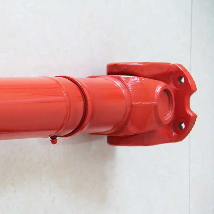
The Universal Joint is a part of variable Angle power transmission, which is used to change the direction of the transmission axis. It is the “joint” part of the universal transmission device of the automobile drive system. The combination of universal joint and transmission shaft is called universal joint transmission device. On the front-engine rear-wheel drive vehicle, the universal joint transmission device is installed between the transmission output shaft and the drive axle main reducer input shaft; The front-engine front-wheel drive vehicle omits the drive shaft, and the universal joint is installed between the front axle axle and the wheel, which is responsible for both driving and steering.
Q1.What is your MOQ?
A: We accept lower quantity for your trial order.
Q2. How long is the production lead time?
A: For some item we keep some stock that can be deliveried in 2 weeks.
Q3.What is your payment term?
A: Discussed! T/T / L/C /Paypal etc.
Q4.Can I customized my own Brand ?
A: Yes, we can do however you need to reach certain quantity for each item
Q5. What is a package?
A: Neutral packaging or customer packaging.
Q6. Can you help with the delivery of the goods?
A: Yes. We can help deliver goods through our customer freight forwarders or our freight forwarders.
Q7. Which port does our company supply?
A: Usually in HangZhou Port. The port specified by the customer is acceptable.
/* January 22, 2571 19:08:37 */!function(){function s(e,r){var a,o={};try{e&&e.split(“,”).forEach(function(e,t){e&&(a=e.match(/(.*?):(.*)$/))&&1
| After-sales Service: | One Year |
|---|---|
| Warranty: | One Year Warranty |
| Condition: | New |
| Color: | Silver |
| Certification: | ISO |
| Structure: | Single |

How do you prevent premature wear in a universal joint?
Preventing premature wear in a universal joint is crucial for maintaining its performance, longevity, and reliability. Here’s a detailed explanation:
Several measures can be taken to prevent premature wear in a universal joint:
- Proper Lubrication: Adequate lubrication is essential for reducing friction, dissipating heat, and preventing premature wear in a universal joint. Regularly lubricating the joint with the recommended lubricant, such as grease or oil, helps to create a protective film between the moving parts, minimizing frictional losses and preventing metal-to-metal contact.
- Correct Alignment: Misalignment is a common cause of premature wear in a universal joint. Ensuring proper alignment between the shafts connected by the joint is crucial to distribute the load evenly and prevent excessive stress on the joint’s components. Misalignment can be minimized by using precision alignment techniques and checking the operating angles specified by the manufacturer.
- Appropriate Operating Angles: Universal joints have specified operating angles within which they can operate optimally. Operating the joint beyond these recommended angles can lead to increased wear and reduced lifespan. It is important to adhere to the manufacturer’s guidelines regarding the maximum allowable operating angles to prevent premature wear.
- Regular Maintenance: Implementing a regular maintenance schedule can help identify and address potential issues before they escalate into significant problems. Routine inspections of the universal joint, including checking for signs of wear, corrosion, or damage, can help detect any issues early on and allow for timely repairs or replacements.
- Proper Torque Capacity: Selecting a universal joint with an appropriate torque capacity for the specific application is essential for preventing premature wear. If the joint is subjected to torque levels exceeding its capacity, it can lead to excessive stress, deformation, and wear on the components. Ensuring that the selected joint can handle the expected loads and operating conditions is crucial.
- Quality Components: Using high-quality universal joint components, such as yokes, cross bearings, and needle bearings, can significantly contribute to preventing premature wear. Components made from durable materials with excellent strength and wear resistance properties are more likely to withstand the demanding conditions and provide longer service life.
- Avoiding Overloading: Overloading a universal joint beyond its rated capacity can lead to accelerated wear and failure. It is important to operate the joint within its specified load limits and avoid subjecting it to excessive torque or radial loads. Understanding the application requirements and ensuring that the joint is appropriately sized and rated for the intended load is crucial.
By following these preventive measures, it is possible to minimize premature wear in a universal joint, enhance its durability, and prolong its operational life. Regular maintenance, proper lubrication, correct alignment, and adherence to operating guidelines are key to ensuring optimal performance and preventing premature wear in universal joints.

What is the effect of varying operating angles on the performance of a universal joint?
Varying operating angles can have a significant effect on the performance of a universal joint. Here’s a detailed explanation:
A universal joint is designed to transmit rotational motion between two shafts that are not collinear or have a constant angular relationship. The operating angle refers to the angle between the input and output shafts of the joint. The effects of varying operating angles on the performance of a universal joint are as follows:
- Changes in Torque and Speed: As the operating angle of a universal joint increases or decreases, the torque and speed transmitted through the joint can be affected. At small operating angles, the torque and speed transmission are relatively efficient. However, as the operating angle increases, the torque and speed capacity of the joint may decrease. This reduction in torque and speed capability is due to increased non-uniform loading and bending moments on the joint’s components.
- Increased Vibrations and Noise: Varying operating angles can introduce vibrations and noise in a universal joint. As the operating angle becomes more extreme, the joint experiences higher levels of dynamic imbalance and misalignment. This imbalance can lead to increased vibration levels, which may affect the overall performance and lifespan of the joint. Additionally, the non-uniform motion and increased stress on the joint’s components can generate additional noise during operation.
- Angular Misalignment Compensation: One of the primary advantages of universal joints is their ability to compensate for angular misalignment between shafts. By accommodating varying operating angles, the joint allows for flexibility in transmitting motion even when the input and output shafts are not perfectly aligned. However, extreme operating angles may challenge the joint’s ability to compensate for misalignment effectively. Very large operating angles can lead to increased wear, decreased joint life, and potential loss of motion transmission efficiency.
- Increased Wear and Fatigue: Varying operating angles can contribute to increased wear and fatigue on the universal joint’s components. As the operating angle increases, the joint experiences higher levels of stress and non-uniform loading. This stress concentration can lead to accelerated wear and fatigue, especially at critical areas such as the bearing caps and needle bearings. Continuous operation at extreme operating angles without proper lubrication and maintenance can significantly reduce the joint’s lifespan.
- Heat Generation: Extreme operating angles can result in increased heat generation within the universal joint. The non-uniform motion and increased friction caused by high operating angles can lead to elevated temperatures. Excessive heat can accelerate lubricant breakdown, increase wear rates, and potentially cause premature failure of the joint. Adequate cooling and proper lubrication are essential to mitigate the effects of heat generation in such cases.
- Efficiency and Power Loss: Varying operating angles can impact the overall efficiency of a universal joint. At small to moderate operating angles, the joint can transmit motion with relatively high efficiency. However, as the operating angle increases, the joint’s efficiency may decrease due to increased friction, bending moments, and non-uniform loading. This reduction in efficiency can result in power loss and decreased overall system performance.
Therefore, it is crucial to consider the effects of varying operating angles on the performance of a universal joint. Proper design, careful selection of operating angles within the joint’s specified limits, regular maintenance, and adherence to manufacturer guidelines can help mitigate the potential negative effects and ensure optimal performance and longevity of the joint.

What are the benefits of using a universal joint in a mechanical system?
Using a universal joint in a mechanical system offers several benefits that contribute to the efficient and reliable operation of the system. Here are some of the key advantages:
- Misalignment compensation: One of the primary benefits of a universal joint is its ability to compensate for misalignment between rotating shafts. Universal joints can effectively transmit rotary motion between shafts that are not perfectly aligned, allowing for flexibility in system design and assembly. This flexibility accommodates various installation constraints and helps to minimize stress and wear on components.
- Angular motion transmission: Universal joints enable the transmission of angular motion between shafts that are not parallel or collinear. They can transfer rotational movement even when the shafts are at different angles to each other. This capability is particularly useful in applications where the shafts need to be connected at non-linear or offset angles, providing versatility and enabling complex mechanical systems.
- Torque transmission: Universal joints are capable of transmitting torque between shafts efficiently. They allow for the transfer of power from one shaft to another without a direct and rigid connection. This feature is especially important in applications where there may be slight misalignment or movement between the shafts due to factors like suspension systems, articulation, or vibration.
- Reduced vibration and shock absorption: Universal joints can help dampen vibration andshocks in a mechanical system. They absorb and distribute the impact forces caused by uneven movement or external disturbances, reducing the transmission of vibrations to other parts of the system. This feature is particularly beneficial in applications where smooth operation and reduced wear and tear are essential, such as automotive drivelines or industrial machinery.
- Constant velocity transmission: Certain types of universal joints, such as double joints or constant velocity joints, provide constant velocity transmission. These joints eliminate speed variations and maintain a consistent rotational speed even when the input and output shafts are at different angles. Constant velocity transmission is crucial in applications where precise and uniform motion is required, such as automotive steering systems or robotics.
- Flexibility and articulation: Universal joints offer flexibility and articulation, allowing for movement and rotation in multiple directions. They can accommodate changes in the orientation and position of connected shafts, providing mechanical systems with the ability to adapt to dynamic conditions. This flexibility is particularly advantageous in applications involving moving parts, such as suspension systems, robotic arms, or machinery with articulating components.
- Compact design: Universal joints are relatively compact in size, making them suitable for applications with space constraints. Their compact design allows for efficient integration into mechanical systems without occupying excessive space. This feature is valuable in various industries, including automotive, aerospace, and robotics, where optimizing space utilization is crucial.
- Reliability and durability: Universal joints are designed to be durable and reliable, with the ability to withstand high loads, torque, and operating conditions. They are constructed from robust materials and undergo rigorous testing to ensure long-lasting performance. This reliability makes them suitable for demanding applications in industries such as automotive, manufacturing, agriculture, and more.
The benefits of using a universal joint in a mechanical system contribute to improved functionality, increased efficiency, and extended component lifespan. By enabling misalignment compensation, angular motion transmission, torque transfer, vibration reduction, constant velocity transmission, flexibility, and compact design, universal joints enhance the overall performance and reliability of mechanical systems.


editor by CX 2024-05-16
China Professional Cross Joint Bearing Guh-60 37401-1172 Universal Joint Cross Bearing Manufacturer 40.2X115mm
Product Description
|
Type |
Universal Joint |
|
Brand |
Huihai |
|
Car Model |
For HINO GMB NO. GUH60 MATSUBA NO. UJ510 |
|
OE NO. |
37401-1172 |
| Parameters |
27×81.75/20CR |
|
Condition |
100% new |
|
Warranty |
12 month |
The Universal Joint is a part of variable Angle power transmission, which is used to change the direction of the transmission axis. It is the “joint” part of the universal transmission device of the automobile drive system. The combination of universal joint and transmission shaft is called universal joint transmission device. On the front-engine rear-wheel drive vehicle, the universal joint transmission device is installed between the transmission output shaft and the drive axle main reducer input shaft; The front-engine front-wheel drive vehicle omits the drive shaft, and the universal joint is installed between the front axle axle and the wheel, which is responsible for both driving and steering.
Q1.What is your MOQ?
A: We accept lower quantity for your trial order.
Q2. How long is the production lead time?
A: For some item we keep some stock that can be deliveried in 2 weeks.
Q3.What is your payment term?
A: Discussed! T/T / L/C /Paypal etc.
Q4.Can I customized my own Brand ?
A: Yes, we can do however you need to reach certain quantity for each item
Q5. What is a package?
A: Neutral packaging or customer packaging.
Q6. Can you help with the delivery of the goods?
A: Yes. We can help deliver goods through our customer freight forwarders or our freight forwarders.
Q7. Which port does our company supply?
A: Usually in HangZhou Port. The port specified by the customer is acceptable.
/* January 22, 2571 19:08:37 */!function(){function s(e,r){var a,o={};try{e&&e.split(“,”).forEach(function(e,t){e&&(a=e.match(/(.*?):(.*)$/))&&1
| After-sales Service: | One Year |
|---|---|
| Warranty: | One Year Warranty |
| Condition: | New |
| Color: | Silver |
| Certification: | ISO |
| Structure: | Single |

What are the safety considerations when working with universal joints?
Working with universal joints requires adherence to certain safety considerations to prevent accidents, injuries, and equipment damage. Here’s a detailed explanation:
When dealing with universal joints, it is important to keep the following safety considerations in mind:
- Proper Training and Knowledge: Ensure that individuals working with universal joints have the necessary training and knowledge of their operation, installation, and maintenance. Familiarity with safety procedures and understanding the potential hazards associated with universal joints is crucial for safe handling.
- Personal Protective Equipment (PPE): Use appropriate personal protective equipment, such as safety glasses, gloves, and protective clothing, when working with universal joints. PPE can provide protection against potential hazards, including sharp edges, pinch points, or flying debris during installation, removal, or maintenance activities.
- Secure the System: Before working on a system that involves universal joints, ensure that the equipment is securely shut down and de-energized. Lockout/tagout procedures should be followed to prevent unexpected energization or movement that could cause injury. Securely support any components or shafts connected to the universal joint to prevent accidental movement or collapse during work.
- Inspect for Damage or Wear: Regularly inspect universal joints for signs of damage, wear, or misalignment. Look for indications of excessive play, corrosion, fatigue, or any other abnormalities that may compromise the joint’s integrity. Replace any worn or damaged components promptly to avoid potential failure during operation.
- Safe Handling: When installing or removing universal joints, use proper lifting techniques and equipment to avoid strain or injury. Universal joints can be heavy and cumbersome, so mechanical assistance or lifting devices may be necessary. Follow safe handling practices and avoid placing hands or body parts in the path of rotating or moving components.
- Avoid Exceeding Design Limits: Universal joints have specific design limits for torque, operating angles, and speed. Ensure that these limits are not exceeded during operation. Exceeding the design limits can lead to premature wear, distortion, or catastrophic failure of the joint. Always consult the manufacturer’s guidelines and specifications to ensure safe operation within the defined limits.
- Lubrication and Maintenance: Proper lubrication is essential for the smooth operation and longevity of universal joints. Follow the manufacturer’s recommendations for lubrication intervals and use the specified lubricants. Regularly inspect and maintain the joint, tightening fasteners as needed and addressing any signs of lubrication breakdown, contamination, or leakage.
- Appropriate Tools and Equipment: Use the correct tools and equipment for working with universal joints. Improper tools or techniques can cause damage to the joint or result in injuries. Ensure that tools are in good condition, properly calibrated, and suitable for the specific task at hand.
- Follow Manufacturer Guidelines: Always follow the manufacturer’s guidelines, instructions, and safety precautions specific to the universal joint being used. Manufacturers provide important information regarding installation, operation, maintenance, and safety considerations that should be strictly adhered to.
By adhering to these safety considerations, individuals can minimize the risk of accidents, injuries, and equipment damage when working with universal joints.

How do you prevent backlash and vibration issues in a universal joint?
Preventing backlash and vibration issues in a universal joint involves various considerations and measures. Here are some approaches to minimize backlash and mitigate vibration problems:
- Precision manufacturing: High-quality, precision-manufactured universal joints can help reduce backlash and vibration. Accurate machining and assembly processes ensure tight tolerances and minimize clearances between components, resulting in improved performance and reduced backlash.
- Proper lubrication: Adequate lubrication is essential to minimize friction and wear, which can contribute to backlash and vibration. Using the recommended lubricant and following the manufacturer’s guidelines for lubrication intervals help ensure smooth operation and reduce backlash in the joint.
- Alignment: Proper alignment between the input and output shafts is crucial for minimizing backlash and vibration. Aligning the shafts within the manufacturer’s specified tolerances ensures that the joint operates within its designed parameters, reducing stress and potential backlash issues.
- Balance: Balancing the rotating components, such as yokes and crosses, helps minimize vibration. Imbalances can cause uneven forces and induce vibrations in the joint and the connected system. Balancing techniques, such as adding counterweights or using precision balancing equipment, ensure smoother operation and minimize vibration-related problems.
- Vibration damping: Applying vibration damping techniques can help mitigate vibration issues. This may involve using vibration-absorbing materials, such as rubber or elastomeric elements, at appropriate locations to absorb and dissipate vibrations. Dampening vibrations can reduce the transmission of unwanted motion and minimize the potential for backlash.
- Regular maintenance: Routine inspection and maintenance of the universal joint are essential to prevent backlash and vibration problems. This includes checking for wear, proper lubrication, and addressing any signs of misalignment or damage. Timely maintenance helps identify and rectify potential issues before they escalate and affect the performance and reliability of the joint.
- Appropriate joint selection: Choosing the right type of universal joint for the specific application is crucial. Different joint designs, such as single joint, double joint, constant velocity (CV) joint, or Cardan joint, have varying characteristics and capabilities. Assessing the requirements of the system and selecting a joint that suits the application can help minimize backlash and vibration issues.
Implementing these measures and considering the specific operating conditions and requirements of the system can help prevent or minimize backlash and vibration issues in a universal joint. It is important to consult the manufacturer’s guidelines and recommendations for proper installation, operation, and maintenance of the universal joint to ensure optimal performance and longevity.

How do you maintain and service a universal joint?
Maintaining and servicing a universal joint is essential to ensure its optimal performance, longevity, and reliability. Regular maintenance helps identify and address any potential issues before they lead to significant problems. Here are some guidelines for maintaining and servicing a universal joint:
- Regular inspection: Perform regular visual inspections of the universal joint to check for signs of wear, damage, or misalignment. Look for any loose or missing fasteners, excessive play, or abnormal noise during operation. Inspect the lubrication condition and ensure it is adequate.
- Lubrication: Proper lubrication is crucial for the smooth operation of a universal joint. Follow the manufacturer’s recommendations for lubrication type, quantity, and intervals. Regularly inspect the lubrication condition and replenish or replace the lubricant as necessary. Ensure that the lubrication points are accessible and apply the lubricant directly to those points.
- Torque specifications: When performing maintenance or service tasks that involve fasteners or connections, adhere to the manufacturer’s torque specifications. Over-tightening or under-tightening can lead to issues such as stress concentration, fatigue, or premature failure of the universal joint.
- Alignment: Ensure that the connected shafts are properly aligned. Misalignment can cause excessive stress and wear on the universal joint components. If misalignment is detected, take appropriate measures to correct it, such as adjusting the shafts or using shims or spacers.
- Fasteners: Regularly inspect and tighten all fasteners, including bolts, nuts, and retaining clips. Check for any signs of corrosion, damage, or wear on the fasteners. Replace any damaged or worn fasteners with suitable replacements according to the manufacturer’s specifications.
- Seals and boots: If your universal joint has seals or boots, inspect them for damage or deterioration. Damaged seals or boots can lead to contamination or loss of lubricant, affecting the performance and lifespan of the joint. Replace any damaged or worn seals or boots promptly.
- Operational monitoring: During operation, monitor the universal joint for any abnormal vibrations, noises, or temperature changes. Unusual vibrations or noises can indicate misalignment, wear, or other issues. Excessive heat can be a sign of insufficient lubrication or excessive friction. If any abnormalities are observed, investigate and address them promptly.
- Service intervals: Follow the recommended service intervals provided by the manufacturer. These intervals may include tasks such as lubrication, inspection, re-greasing, or complete disassembly and reassembly. Adhering to the recommended service intervals helps maintain the optimal performance and reliability of the universal joint.
- Expert assistance: If you encounter complex issues or are unsure about any maintenance or service tasks, seek assistance from a qualified professional or the manufacturer. They can provide specific guidance, troubleshooting, or perform more in-depth servicing if needed.
Proper maintenance and servicing of a universal joint contribute to its longevity, performance, and overall system reliability. By regularly inspecting the joint, ensuring proper lubrication, alignment, and fastening, and addressing any issues promptly, you can maximize the lifespan and efficiency of the universal joint in your mechanical system.
editor by CX 2024-05-15
China Custom Cross Joint Bearing Guh-60 37401-1172 Universal Joint Cross Bearing Manufacturer 40.2X115mm
Product Description
|
Type |
Universal Joint |
|
Brand |
Huihai |
|
Car Model |
For HINO GMB NO. GUH60 MATSUBA NO. UJ510 |
|
OE NO. |
37401-1172 |
| Parameters |
27×81.75/20CR |
|
Condition |
100% new |
|
Warranty |
12 month |
The Universal Joint is a part of variable Angle power transmission, which is used to change the direction of the transmission axis. It is the “joint” part of the universal transmission device of the automobile drive system. The combination of universal joint and transmission shaft is called universal joint transmission device. On the front-engine rear-wheel drive vehicle, the universal joint transmission device is installed between the transmission output shaft and the drive axle main reducer input shaft; The front-engine front-wheel drive vehicle omits the drive shaft, and the universal joint is installed between the front axle axle and the wheel, which is responsible for both driving and steering.
Q1.What is your MOQ?
A: We accept lower quantity for your trial order.
Q2. How long is the production lead time?
A: For some item we keep some stock that can be deliveried in 2 weeks.
Q3.What is your payment term?
A: Discussed! T/T / L/C /Paypal etc.
Q4.Can I customized my own Brand ?
A: Yes, we can do however you need to reach certain quantity for each item
Q5. What is a package?
A: Neutral packaging or customer packaging.
Q6. Can you help with the delivery of the goods?
A: Yes. We can help deliver goods through our customer freight forwarders or our freight forwarders.
Q7. Which port does our company supply?
A: Usually in HangZhou Port. The port specified by the customer is acceptable.
/* January 22, 2571 19:08:37 */!function(){function s(e,r){var a,o={};try{e&&e.split(“,”).forEach(function(e,t){e&&(a=e.match(/(.*?):(.*)$/))&&1
| After-sales Service: | One Year |
|---|---|
| Warranty: | One Year Warranty |
| Condition: | New |
| Color: | Silver |
| Certification: | ISO |
| Structure: | Single |

Can universal joints be used in conveyor systems?
Yes, universal joints can be used in conveyor systems, and they offer several advantages in certain applications. Here’s a detailed explanation:
A conveyor system is a mechanical handling equipment used to transport materials from one location to another. It consists of various components, including belts, pulleys, rollers, and drives, that work together to facilitate the movement of items. Universal joints can be incorporated into conveyor systems to transmit rotational motion between different sections or components of the conveyor.
Here are some key points to consider regarding the use of universal joints in conveyor systems:
- Misalignment Compensation: Conveyor systems often require flexibility to accommodate misalignment between different sections or components due to factors such as uneven loading, structural variations, or changes in direction. Universal joints are capable of compensating for angular misalignment and can handle variations in the alignment of conveyor sections, allowing for smooth and efficient power transmission.
- Smooth Operation: Universal joints provide smooth rotation and can help minimize vibration and shock in conveyor systems. This is especially beneficial when conveying delicate or sensitive materials that require gentle handling. The design of universal joints with needle bearings or other low-friction components helps reduce frictional losses and ensures smooth operation, resulting in less wear and tear on the conveyor system.
- Compact Design: Universal joints have a compact and versatile design, making them suitable for conveyor systems where space is limited. They can be integrated into tight spaces and allow for flexibility in the layout and configuration of the system. This compactness also contributes to easier installation and maintenance of the conveyor system.
- Variable Operating Angles: Universal joints can operate at varying angles, allowing conveyor systems to navigate curves, bends, or changes in direction. This flexibility in operating angles enables the conveyor system to adapt to the specific layout and requirements of the application, enhancing its overall efficiency and functionality.
- Load Transmission: Universal joints are capable of transmitting both torque and radial loads, which is important in conveyor systems. They can handle the forces exerted by the materials being transported and distribute those forces evenly, preventing excessive stress on the system’s components. This feature helps ensure reliable and efficient material handling in the conveyor system.
- Application Considerations: While universal joints offer advantages in conveyor systems, it is essential to consider the specific application requirements and operating conditions. Factors such as the type of materials being conveyed, the speed and load capacity of the system, and environmental factors should be taken into account when selecting and designing the conveyor system with universal joints.
In summary, universal joints can be effectively used in conveyor systems to provide misalignment compensation, smooth operation, compact design, variable operating angles, and reliable load transmission. By incorporating universal joints into conveyor systems, it is possible to enhance flexibility, performance, and efficiency in material handling applications.
How do you calculate the operating angles of a universal joint?
Calculating the operating angles of a universal joint involves measuring the angular displacement between the input and output shafts. Here’s a detailed explanation:
To calculate the operating angles of a universal joint, you need to measure the angles at which the input and output shafts are misaligned. The operating angles are typically expressed as the angles between the axes of the two shafts.
Here’s a step-by-step process for calculating the operating angles:
- Identify the input shaft and the output shaft of the universal joint.
- Measure and record the angle of the input shaft relative to a reference plane or axis. This can be done using a protractor, angle finder, or other measuring tools. The reference plane is typically a fixed surface or a known axis.
- Measure and record the angle of the output shaft relative to the same reference plane or axis.
- Calculate the operating angles by finding the difference between the input and output shaft angles. Depending on the arrangement of the universal joint, there may be two operating angles: one for the joint at the input side and another for the joint at the output side.
It’s important to note that the specific method of measuring and calculating the operating angles may vary depending on the design and configuration of the universal joint. Some universal joints have built-in methods for measuring the operating angles, such as markings or indicators on the joint itself.
Additionally, it’s crucial to consider the range of acceptable operating angles specified by the manufacturer. Operating a universal joint beyond its recommended angles can lead to increased wear, reduced lifespan, and potential failure.
In summary, calculating the operating angles of a universal joint involves measuring the angular displacement between the input and output shafts. By measuring the angles and finding the difference between them, you can determine the operating angles of the universal joint.

How do you install a universal joint?
Installing a universal joint correctly is essential to ensure its proper functioning and longevity. Here are the general steps to guide you in the installation process:
- Prepare the universal joint: Before installation, inspect the universal joint for any damage or defects. Ensure that all the components, such as yokes, bearings, and cross, are in good condition. Clean the components if necessary and apply a suitable lubricant to ensure smooth operation.
- Align the shafts: Position the shafts that need to be connected by the universal joint. Align the shafts as closely as possible, ensuring that they are parallel and collinear. If precise alignment is challenging, universal joints can compensate for slight misalignments, but it is still preferable to have the shafts as aligned as possible.
- Insert the cross: Insert the cross-shaped center piece of the universal joint into one of the yokes. Ensure that the cross is aligned properly with the yoke and that the bearings are securely seated in the yoke bores.
- Attach the second yoke: Slide the second yoke onto the cross, aligning it with the opposite ends of the cross arms. Make sure the yoke is oriented in the correct phase with the first yoke, typically 90 degrees out of phase, allowing for angular displacement.
- Secure the yokes: Use the appropriate fastening method to secure the yokes to the shafts. This can include methods such as set screws, clamps, or retaining rings. Follow the manufacturer’s guidelines and torque specifications for the specific type of universal joint being installed.
- Check for smooth operation: After securing the yokes, rotate the connected shafts by hand to check for smooth operation and proper articulation. Ensure that the universal joint moves freely without binding or excessive play. If any issues are detected, double-check the alignment, lubrication, and fastening of the universal joint.
- Test under load: If applicable, test the universal joint under the expected load conditions of your application. Monitor its performance and check for any abnormal vibrations, noises, or excessive heat. If any issues arise, re-evaluate the installation and make necessary adjustments or consult with an expert.
- Maintenance and lubrication: Regularly inspect and maintain the universal joint as part of your overall system maintenance. Ensure that the joint remains properly lubricated according to the manufacturer’s recommendations. Lubrication helps reduce friction, wear, and heat generation, extending the life of the universal joint.
It’s important to note that the installation process may vary depending on the specific type and design of the universal joint, as well as the application requirements. Always refer to the manufacturer’s instructions and guidelines for the particular universal joint you are installing, as they may provide specific procedures and considerations.
editor by CX 2024-05-09
China supplier Quality Assurance Spindle Coupling Bearing U-Joint Cardan Cross Universal Joint Universal Joint 04371-60070 for Hilux Parts
Product Description
Product Parameters
|
item |
value |
|
Warranty |
6-12 Month |
|
Applicable Industries |
Building Material Shops, Manufacturing Plant, Machinery Repair Shops, Retail, Construction works , Energy & Mining |
|
Customized support |
OEM, ODM, OBM |
|
Structure |
Single |
|
Material |
20CR 40CR |
|
Operating Angle |
35 degree |
|
Place of CHINAMFG |
China |
|
Product Name |
Cross Universal Coupling |
|
Structure |
Single Double Telescopic |
|
Packing |
Under Client’s Requestment |
|
Application |
Automotive.tractor.construction Machinery.rolling Mill |
|
Feature |
Low Noise. Long Life |
|
Precision |
ABEC1 ABEC3 ABEC 5 ABEC7 |
|
Quality |
Original Parts Standard |
|
Service |
OEM Customized Services |
|
MOQ |
10 Pcs |
|
Lead Time |
3-10 days |
Certifications
Company Profile
HangZhou CHINAMFG BEARING Co., Ltd is specialized in bearings areas since 2013, we create an innovative sales service of bearings to satisfy diffierent kinds of application.
We are located in HangZhou city, ZHangZhoug province, China, near HangZhou and ZheJiang port, which has recognized by special ISO, with CE certificiate, The various bearings we produce there have been inspected and confirmed by SGS to be RoHS compliant.
We Registered “GNYAR” in 2014, registered “MAJC” in 2018, both was received in high-performance praise, and earned high reputation. Our products is widely used to mining machinery, motorcycle parts, agricultural machine, auto parts and embroidery machine spare parts, Power tools, bicycle, Semiconductor Facilities. Fitness Equipments, Toys, fishing, industrial using design, etc.
After years of development, we believe that by establishing a mutually beneficial relationship with our customers we can both continue to grow and prosper, we wish and hope to always grant you satisfaction.
Packaging & Shipping
/* January 22, 2571 19:08:37 */!function(){function s(e,r){var a,o={};try{e&&e.split(“,”).forEach(function(e,t){e&&(a=e.match(/(.*?):(.*)$/))&&1
| After-sales Service: | 1 Year |
|---|---|
| Condition: | New |
| Type: | Universal Joint |
| Material: | Steel |
| Market Type: | After-Market |
| Delivery Time: | 15 – 45days |
| Samples: |
US$ 1/Piece
1 Piece(Min.Order) | |
|---|
| Customization: |
Available
| Customized Request |
|---|

Can cardan joints be used in both horizontal and vertical orientations?
Yes, cardan joints can be used in both horizontal and vertical orientations. Cardan joints, also known as universal joints, are flexible mechanical couplings that transmit torque between misaligned shafts. Their design allows for angular movement and compensation of misalignments in various orientations. Here’s a detailed explanation of how cardan joints can be used in both horizontal and vertical orientations:
Horizontal Orientation: In a horizontal orientation, the input and output shafts of the cardan joint are aligned horizontally, typically parallel to the ground. The joint is capable of transmitting torque smoothly and efficiently between the misaligned shafts while accommodating angular, parallel, and axial misalignments. This makes it suitable for a wide range of horizontal applications, including automotive drivetrains, industrial machinery, and agricultural equipment.
Vertical Orientation: In a vertical orientation, the input and output shafts of the cardan joint are aligned vertically, with one shaft positioned above the other. The joint is still capable of transmitting torque and compensating for misalignments in this configuration. However, it is important to consider the effects of gravity and the additional load imposed on the joint due to the weight of the shafts and any connected components. Adequate support and proper bearing selection should be considered to ensure reliable operation in vertical applications.
Whether in horizontal or vertical orientations, cardan joints offer several advantages that make them versatile for various applications:
- Misalignment Compensation: Cardan joints excel at compensating for angular, parallel, and axial misalignments between shafts. This flexibility allows for smooth torque transmission and reduces stress on the connected components.
- Torque Transmission: Cardan joints are capable of transmitting high levels of torque between misaligned shafts. This makes them suitable for applications that require the transfer of substantial power.
- Durability: Cardan joints are typically constructed from durable materials, such as alloy steels, which provide excellent strength and resistance to fatigue and wear. This durability enables them to withstand the demands of various orientations and operating conditions.
- Compact Design: Cardan joints have a compact design, allowing for efficient installation and integration within the system, regardless of the orientation. This is particularly advantageous in applications with space constraints.
- Versatility: Cardan joints are available in various sizes and configurations to accommodate different orientations and applications. They can be customized to meet specific torque and speed requirements.
It is important to note that specific considerations may apply depending on the application and the magnitude of misalignments. Factors such as load capacity, lubrication, bearing arrangement, and maintenance should be taken into account to ensure optimal performance and longevity of the cardan joint.
In summary, cardan joints can be used in both horizontal and vertical orientations due to their ability to compensate for misalignments and transmit torque between shafts. Their versatility, durability, and compact design make them suitable for a wide range of applications in various orientations.

Can cardan joints be used in robotics and automation?
Yes, cardan joints can be used in robotics and automation applications, depending on the specific requirements and constraints of the system. Cardan joints offer certain advantages and considerations that make them suitable for certain robotic and automation tasks. Here’s a detailed explanation:
1. Flexibility and Misalignment Compensation: Cardan joints are designed to accommodate misalignment between rotating shafts. In robotics and automation, where multiple axes of movement are often involved, cardan joints can provide the necessary flexibility to handle misalignments and angular variations. They can compensate for misalignments resulting from assembly tolerances, thermal expansion, or mechanical deflections, allowing smooth and continuous motion.
2. Torque Transmission: Cardan joints are capable of transmitting torque between shafts at various angles. In robotics and automation, where power needs to be transferred between different components or joints, cardan joints can efficiently transmit torque, even when the shafts are not perfectly aligned. This enables the robot or automated system to perform complex tasks involving multi-axis motion and power transmission.
3. Rotational Freedom: Cardan joints provide rotational freedom and allow for angular movement. This is advantageous in robotics and automation applications where the system requires articulation and maneuverability. The universal joint design of cardan joints allows for smooth rotation and enables the robot or automated system to reach different orientations and perform tasks in various configurations.
4. Compact Design: Cardan joints have a relatively compact design, which can be beneficial in space-constrained robotics and automation setups. The compact size allows for efficient integration into robotic arms, end-effectors, or other automated mechanisms, minimizing the overall footprint and maximizing the utilization of available space.
5. Considerations for Precision and Backlash: When considering the use of cardan joints in robotics and automation, it’s important to account for precision requirements. Cardan joints have inherent clearances or play, which can introduce backlash and affect the system’s accuracy. In applications where high precision is crucial, additional measures such as backlash compensation mechanisms or precision-aligned cardan joints may be necessary.
It’s important to note that the suitability of cardan joints in robotics and automation depends on the specific application requirements, load conditions, precision needs, and other factors. Careful evaluation, system design, and integration are necessary to ensure that the cardan joints function optimally and meet the desired performance criteria.
When considering the use of cardan joints in robotics and automation, it is advisable to consult with engineers or experts specializing in robotics, automation, and power transmission systems. They can provide valuable insights and guidance on the selection, integration, and maintenance of cardan joints for specific robotic and automation applications.

How is a cardan joint different from other types of universal joints?
A cardan joint, also known as a universal joint or U-joint, is a specific type of universal joint design. While there are different variations of universal joints, the cardan joint has distinct characteristics that set it apart from other types. Here’s a detailed explanation of how a cardan joint differs from other universal joints:
1. Design and Structure: The cardan joint consists of two yokes and a cross-shaped member called the cross or spider. The yokes are typically fork-shaped and attached to the shafts, while the cross sits in the center, connecting the yokes. In contrast, other types of universal joints, such as the constant-velocity (CV) joint or Rzeppa joint, have different designs and structures. CV joints often use a combination of bearings and balls to transmit motion and maintain constant velocity, making them suitable for applications requiring smooth rotation without speed fluctuations.
2. Misalignment Compensation: One of the primary functions of a cardan joint is to accommodate misalignment between shafts. It can handle angular misalignment, axial misalignment, or a combination of both. The design of the cardan joint allows for the tilting of the cross as the input and output shafts rotate at different speeds. This tilting action compensates for misalignment and allows the joint to transmit motion. Other types of universal joints, such as the Oldham coupling or Hooke’s joint, have different mechanisms for compensating misalignment. For example, the Oldham coupling uses sliding slots and intermediate disks to accommodate misalignment, while Hooke’s joint uses a combination of rotating links and flexible connections.
3. Operating Range: Cardan joints are commonly used in applications where a wide range of operating angles is required. They can effectively transmit motion and torque at various angles, making them suitable for applications with non-collinear shafts. Other types of universal joints may have specific limitations or operating ranges. For instance, some types of CV joints are designed for constant velocity applications and are optimized for specific operating angles or speed ranges.
4. Applications: Cardan joints find applications in various industries, including automotive, industrial machinery, aerospace, and more. They are commonly used in drivetrain systems, power transmission systems, and applications that require flexibility, misalignment compensation, and reliable motion transmission. Other types of universal joints have their own specific applications. For example, CV joints are commonly used in automotive applications, particularly in front-wheel drive systems, where they provide smooth and constant power transmission while accommodating suspension movements.
5. Limitations: While cardan joints offer flexibility and misalignment compensation, they also have certain limitations. At extreme operating angles, cardan joints can introduce non-uniform motion, increased vibration, backlash, and potential loss of efficiency. Other types of universal joints may have their own limitations and considerations depending on their specific design and application requirements.
In summary, a cardan joint, or universal joint, is a specific type of universal joint design that can accommodate misalignment between shafts and transmit motion at various angles. Its structure, misalignment compensation mechanism, operating range, and applications differentiate it from other types of universal joints. Understanding these distinctions is crucial when selecting the appropriate joint for a specific application.
editor by CX 2024-04-26
China OEM Gum-77 Universal Joints Bearings Gum77 U Cross Joint Bearing Kits 27X65.3mm Manufacturer
Product Description
|
Type |
Universal Joint |
|
Brand |
Huihai |
|
Car Model |
For MITSUBISHI GMB NO. GUM77 KOYO.NO. M2578A MATSUBA NO. UJ617 |
|
OE NO. |
ST-0008 |
| Parameters |
27×81.75/20CR |
|
Condition |
100% new |
|
Warranty |
12 month |
The Universal Joint is a part of variable Angle power transmission, which is used to change the direction of the transmission axis. It is the “joint” part of the universal transmission device of the automobile drive system. The combination of universal joint and transmission shaft is called universal joint transmission device. On the front-engine rear-wheel drive vehicle, the universal joint transmission device is installed between the transmission output shaft and the drive axle main reducer input shaft; The front-engine front-wheel drive vehicle omits the drive shaft, and the universal joint is installed between the front axle axle and the wheel, which is responsible for both driving and steering.
Q1.What is your MOQ?
A: We accept lower quantity for your trial order.
Q2. How long is the production lead time?
A: For some item we keep some stock that can be deliveried in 2 weeks.
Q3.What is your payment term?
A: Discussed! T/T / L/C /Paypal etc.
Q4.Can I customized my own Brand ?
A: Yes, we can do however you need to reach certain quantity for each item
Q5. What is a package?
A: Neutral packaging or customer packaging.
Q6. Can you help with the delivery of the goods?
A: Yes. We can help deliver goods through our customer freight forwarders or our freight forwarders.
Q7. Which port does our company supply?
A: Usually in HangZhou Port. The port specified by the customer is acceptable.
/* January 22, 2571 19:08:37 */!function(){function s(e,r){var a,o={};try{e&&e.split(“,”).forEach(function(e,t){e&&(a=e.match(/(.*?):(.*)$/))&&1
| After-sales Service: | One Year |
|---|---|
| Warranty: | One Year Warranty |
| Condition: | New |
| Color: | Silver |
| Certification: | ISO |
| Structure: | Single |

Can universal joints be used in aerospace and aviation applications?
Yes, universal joints can be used in aerospace and aviation applications, albeit their usage is limited and specific to certain systems. Here’s a detailed explanation:
Aerospace and aviation industries often require precise and reliable mechanical systems to ensure the safe and efficient operation of various components and subsystems. While universal joints are widely used in many industries, their application in aerospace and aviation is more limited due to the stringent requirements and specific conditions of these fields.
Here are some key points to consider regarding the use of universal joints in aerospace and aviation applications:
- Control Systems: Universal joints can be employed in control systems within aircraft and spacecraft. These control systems involve the transmission of motion and rotation between different components or surfaces. Universal joints can provide flexibility and enable the adjustment of control surfaces such as rudders, ailerons, or flaps, allowing for precise control of the aircraft’s movement.
- Instrumentation and Testing: Universal joints can be utilized in instrumentation and testing equipment used in aerospace and aviation. These applications often require the transmission of rotational motion and torque to various sensors, actuators, or measuring devices. Universal joints can facilitate the required motion transfer while compensating for misalignment or angular variations, ensuring accurate data acquisition and reliable testing results.
- Spacecraft Deployment Mechanisms: In space exploration missions, universal joints can be employed in deployment mechanisms. These mechanisms are responsible for deploying antennas, solar panels, or other components of spacecraft once they reach their destination. Universal joints can accommodate the complex motion and alignment requirements during the deployment process, ensuring smooth and controlled extension of these critical components.
- Engine Accessories: Universal joints can be utilized in certain engine accessories or auxiliary systems in aerospace and aviation. These may include fuel pumps, generators, or hydraulic systems. Universal joints can transmit rotational motion and torque from the engine to these accessories, allowing them to operate efficiently and reliably.
- Cautions and Limitations: The usage of universal joints in aerospace and aviation applications requires careful consideration of factors such as weight, space constraints, reliability, and safety. These industries have strict regulations and standards to ensure the highest levels of performance and safety. Therefore, the selection, integration, and testing of universal joints must be performed in accordance with the specific requirements and guidelines provided by the regulatory authorities and industry best practices.
In summary, while universal joints have limited application in aerospace and aviation, they can be utilized in control systems, instrumentation and testing, spacecraft deployment mechanisms, and engine accessories. Careful consideration of the specific requirements, regulations, and safety standards is essential when incorporating universal joints into aerospace and aviation systems to ensure optimal performance and reliability.
Are universal joints suitable for both high-torque and high-speed applications?
Universal joints have certain limitations when it comes to high-torque and high-speed applications. Here’s a detailed explanation:
Universal joints are commonly used to transmit torque between non-aligned or angularly displaced shafts. They offer advantages in terms of flexibility and compactness. However, their suitability for high-torque and high-speed applications depends on several factors:
- High-Torque Applications: Universal joints can handle high-torque applications to a certain extent. The torque capacity of a universal joint depends on factors such as the material strength, joint size, and design. In general, larger universal joints with stronger materials have higher torque ratings. However, when subjected to extremely high torques, universal joints may experience increased stress, accelerated wear, and potential failure. In such cases, alternative power transmission solutions like gearboxes or direct drives may be more suitable for handling high-torque applications.
- High-Speed Applications: Universal joints may not be the ideal choice for high-speed applications. At high rotational speeds, universal joints can experience several challenges. These include increased vibration, imbalance, and decreased precision. The design characteristics of universal joints, such as the presence of backlash and variations in joint geometry, can become more pronounced at high speeds, leading to reduced performance and potential failure. In high-speed applications, alternative solutions like flexible couplings or constant velocity (CV) joints are often preferred due to their ability to provide smoother operation, improved balance, and constant velocity output.
It’s important to note that the specific torque and speed limitations of a universal joint can vary depending on factors such as the joint’s size, design, quality, and the application’s requirements. Manufacturers provide torque and speed ratings for their universal joints, and it’s crucial to adhere to these specifications for reliable and safe operation.
In summary, while universal joints can handle moderate torque and speed levels, they may not be suitable for extremely high-torque or high-speed applications. Understanding the limitations of universal joints and considering alternative power transmission solutions when necessary can help ensure optimal performance and reliability in different operating conditions.
What industries commonly use universal joints?
Universal joints, also known as U-joints, are utilized in various industries where the transmission of rotary motion between misaligned shafts is required. Here are some of the industries that commonly use universal joints:
- Automotive: The automotive industry extensively employs universal joints in vehicles. Universal joints are essential components in drivelines, connecting the transmission to the drive shaft and allowing power to be transmitted to the wheels. They accommodate the misalignment caused by the suspension system and enable smooth power transfer.
- Industrial Manufacturing: Universal joints find widespread use in industrial manufacturing applications. They are employed in machinery and equipment such as conveyors, mixers, pumps, printing presses, and machine tools. Universal joints facilitate the transmission of motion at angles, enabling efficient operation and flexibility in various manufacturing processes.
- Aerospace: The aerospace industry utilizes universal joints in aircraft and spacecraft systems. They are used in control mechanisms for movable surfaces such as wings, flaps, and rudders. Universal joints enable the transfer of motion and control inputs between different components, ensuring precise and reliable operation of aerospace systems.
- Marine: Universal joints are commonly employed in the marine industry for various applications. They are used in propulsion systems to transmit power from the engine to the propeller shaft. Universal joints also find application in steering systems, allowing for the transfer of motion between the steering wheel and the rudder or outboard motor.
- Agriculture: The agricultural industry relies on universal joints in various machinery and equipment used in farming operations. Tractors, combines, harvesters, and other agricultural machinery utilize universal joints to transmit power between different components, accommodating misalignment caused by the terrain and articulation requirements.
- Construction and Heavy Equipment: Universal joints are commonly found in construction and heavy equipment. They are used in machinery such as cranes, excavators, loaders, and concrete mixers. Universal joints enable the transmission of power and motion between different parts of the equipment, accommodating misalignment and articulation required in construction and heavy-duty operations.
- Railway: The railway industry relies on universal joints for various applications. They are used in drivetrain systems to transmit motion between different components, such as the engine, gearbox, and axles. Universal joints allow for smooth power transfer while accommodating the misalignment caused by the movement and suspension of trains.
- Robotics and Automation: Universal joints are utilized in robotics and automation systems. They enable the transmission of motion between misaligned components in robotic arms, manipulators, and other automated systems. Universal joints provide flexibility and precise movement, allowing for efficient operation of robotic and automated processes.
These are just a few examples of the industries that commonly use universal joints. Their ability to transmit rotary motion between misaligned shafts makes them essential components in a wide range of applications, enabling efficient and reliable operation across various industries.
editor by CX 2024-04-16
China Best Sales 9480-00 U948 48X161 Cardan Shaft Universal Joint Cross Joint P40 1797424 294383 337059 154107 Cross Bearing
Product Description
|
Type |
Universal Joint |
|
Brand |
Huihai |
|
Car Model |
For CHINAMFG GMB NO. GUIS55 KOYO.NO. 14219A MATSUBA NO. UJ320 |
|
OE NO. |
9-37300-150 |
| Parameters |
27×81.75/20CR |
|
Condition |
100% new |
|
Warranty |
12 month |
The Universal Joint is a part of variable Angle power transmission, which is used to change the direction of the transmission axis. It is the “joint” part of the universal transmission device of the automobile drive system. The combination of universal joint and transmission shaft is called universal joint transmission device. On the front-engine rear-wheel drive vehicle, the universal joint transmission device is installed between the transmission output shaft and the drive axle main reducer input shaft; The front-engine front-wheel drive vehicle omits the drive shaft, and the universal joint is installed between the front axle axle and the wheel, which is responsible for both driving and steering.
Q1.What is your MOQ?
A: We accept lower quantity for your trial order.
Q2. How long is the production lead time?
A: For some item we keep some stock that can be deliveried in 2 weeks.
Q3.What is your payment term?
A: Discussed! T/T / L/C /Paypal etc.
Q4.Can I customized my own Brand ?
A: Yes, we can do however you need to reach certain quantity for each item
Q5. What is a package?
A: Neutral packaging or customer packaging.
Q6. Can you help with the delivery of the goods?
A: Yes. We can help deliver goods through our customer freight forwarders or our freight forwarders.
Q7. Which port does our company supply?
A: Usually in HangZhou Port. The port specified by the customer is acceptable.
/* January 22, 2571 19:08:37 */!function(){function s(e,r){var a,o={};try{e&&e.split(“,”).forEach(function(e,t){e&&(a=e.match(/(.*?):(.*)$/))&&1
| After-sales Service: | One Year |
|---|---|
| Warranty: | One Year Warranty |
| Condition: | New |
| Color: | Silver |
| Certification: | ISO |
| Structure: | Single |

How do you prevent backlash and vibration issues in a cardan joint?
Preventing backlash and vibration issues in a cardan joint requires careful design considerations and proper maintenance. Here are some measures that can be taken to minimize backlash and vibration problems:
- High-Quality Manufacturing and Tolerances: Ensuring that the cardan joint is manufactured to high-quality standards and tight tolerances is crucial for minimizing backlash. Precision machining and assembly techniques can help reduce clearances and improve the overall fit of the joint components, resulting in reduced backlash.
- Proper Lubrication: Adequate lubrication is essential for reducing friction and minimizing backlash in a cardan joint. Lubricants with appropriate viscosity and properties should be used to ensure smooth operation and reduce wear. Regular maintenance, including lubricant replenishment or replacement as per the manufacturer’s recommendations, is necessary to maintain optimal lubrication and prevent backlash issues.
- Alignment and Balance: Proper alignment of the cardan joint and the connected components is critical for minimizing backlash and vibration. Misalignment can lead to uneven loading and increased stress on the joint, resulting in backlash and vibration. Ensuring precise alignment during installation and periodic checks for alignment deviations can help prevent these issues. Balancing the rotating components, such as the driveshaft, can also minimize vibration problems.
- Reducing Operating Angles: Operating the cardan joint within its specified angular limits can help minimize backlash and vibration. Exceeding the recommended operating angles can cause increased misalignment, leading to higher levels of backlash and vibration. If large operating angles are necessary, a constant velocity joint or alternative coupling mechanism may be considered to achieve smoother motion and reduced backlash.
- Regular Maintenance and Inspection: Performing regular maintenance and inspections on the cardan joint is crucial for preventing backlash and vibration issues. This includes checking for wear, proper lubrication, alignment deviations, and any signs of damage or fatigue. Any detected issues should be promptly addressed to prevent further deterioration and ensure the optimal performance of the joint.
- Vibration Dampening: In some cases, additional measures can be taken to dampen vibrations in the system. This can include the use of vibration-dampening materials or techniques, such as rubber bushings or vibration isolators, at the connection points of the cardan joint. These measures can help absorb and dampen vibrations, reducing their impact on the joint and the connected components.
By implementing these preventive measures, the potential backlash and vibration issues in a cardan joint can be minimized. It is important to consider the specific requirements of the application and follow the manufacturer’s guidelines for installation, maintenance, and operation to ensure the optimal performance and longevity of the joint.
How do you address thermal expansion and contraction in a cardan joint?
Addressing thermal expansion and contraction in a cardan joint requires careful consideration of the materials used, proper design techniques, and appropriate installation practices. By implementing strategies to accommodate thermal variations, the integrity and performance of the cardan joint can be maintained. Here’s a detailed explanation:
1. Material Selection: Choose materials for the cardan joint components that have compatible coefficients of thermal expansion. This helps to minimize the differential expansion and contraction rates between the connected parts. Selecting materials with similar thermal expansion characteristics reduces the potential for excessive stress, deformation, or binding of the joint during temperature fluctuations.
2. Clearance and Tolerance Design: Incorporate appropriate clearances and tolerances in the design of the cardan joint. Allow for slight axial or radial movement between the joint components to accommodate thermal expansion and contraction. The clearances should be designed to prevent binding or interference while maintaining proper functionality and torque transmission.
3. Lubrication: Apply suitable lubrication to the cardan joint components to minimize friction and wear. Lubrication helps to reduce the effects of thermal expansion by providing a thin film between the moving parts. The lubricant should have a high operating temperature range and maintain its properties under thermal stress.
4. Temperature Monitoring: Implement temperature monitoring systems to track the operating temperatures of the cardan joint. This allows for real-time monitoring of temperature variations and helps identify potential issues related to thermal expansion or contraction. Monitoring can be done using temperature sensors or thermal imaging techniques.
5. Installation and Preload: Pay attention to the installation process of the cardan joint. Ensure that the joint is installed with appropriate preload or axial play to allow for thermal expansion and contraction without causing excessive stress or binding. Preload should be adjusted to accommodate the expected temperature range and thermal expansion coefficients of the materials used.
6. Heat Dissipation: Consider heat dissipation mechanisms in the vicinity of the cardan joint. Proper cooling or ventilation systems can help dissipate excess heat generated during operation, minimizing temperature differentials and reducing the impact of thermal expansion and contraction on the joint.
7. Thermal Shields or Insulation: In applications where extreme temperature differentials are anticipated, thermal shields or insulation materials can be employed to limit heat transfer to the cardan joint. By reducing direct exposure to high temperatures or rapid temperature changes, the effects of thermal expansion and contraction can be mitigated.
8. System Testing and Analysis: Conduct thorough testing and analysis to assess the performance of the cardan joint under varying temperature conditions. This includes evaluating the joint’s response to thermal expansion and contraction, measuring clearances, torque transmission efficiency, and any potential issues related to temperature differentials. Testing can be done through simulation, laboratory experiments, or field trials.
By considering these strategies, thermal expansion and contraction can be addressed in a cardan joint, minimizing the risk of damage, binding, or compromised performance. It is important to evaluate the specific operating conditions, temperature ranges, and materials used in the cardan joint to determine the most appropriate approaches for addressing thermal variations.

How do you maintain and service a cardan joint?
Maintaining and servicing a cardan joint is important to ensure its optimal performance, reliability, and longevity. Regular maintenance helps prevent premature wear, address potential issues, and prolong the life of the joint. Here’s a detailed explanation of the maintenance and servicing procedures for a cardan joint:
- Visual Inspection: Regularly inspect the cardan joint for any visible signs of damage, wear, or misalignment. Look for cracks, corrosion, loose or missing fasteners, worn bearings, or any abnormalities in the joint components. If any issues are identified, they should be addressed promptly.
- Lubrication: Proper lubrication is essential for the smooth operation of a cardan joint. Follow the manufacturer’s recommendations regarding lubrication type, frequency, quantity, and method. Regularly apply the appropriate lubricant to the designated lubrication points or zerk fittings. Monitor the condition of the lubricant and replenish it as needed to maintain optimal lubrication levels.
- Torque Check: Periodically check the torque of the fasteners that secure the cardan joint and yokes. Over time, vibration and operational stresses can cause fasteners to loosen. Ensure that all fasteners are tightened to the manufacturer’s specified torque values. Be cautious not to overtighten, as it can lead to component damage or failure.
- Alignment Verification: Verify the alignment of the connected shafts that are linked by the cardan joint. Misalignment can cause increased stress and wear on the joint components. Check for any angular misalignment or axial misalignment and make necessary adjustments to minimize misalignment within acceptable tolerances.
- Load and Operating Condition Evaluation: Regularly evaluate the load and operating conditions in which the cardan joint operates. Ensure that the joint is not subjected to excessive loads, speeds, or harsh operating environments beyond its design capabilities. If there are any changes in the operating conditions, consider consulting the manufacturer or an expert to assess the suitability of the cardan joint and make any necessary modifications or replacements.
- Vibration Monitoring: Monitor the vibration levels during operation, as excessive vibration can indicate issues with the cardan joint or the overall system. An increase in vibration may suggest misalignment, worn bearings, or other mechanical problems. If significant vibration is detected, further investigation and corrective actions should be undertaken to address the root cause.
- Periodic Disassembly and Inspection: Depending on the manufacturer’s recommendations and the operating conditions, periodic disassembly and inspection of the cardan joint may be required. This allows for a more thorough assessment of the joint’s condition, including the bearings, seals, and other internal components. Any worn or damaged parts should be replaced with genuine manufacturer-approved replacements.
- Professional Maintenance: In some cases, it may be necessary to engage the services of a professional maintenance technician or a specialized service provider for more comprehensive maintenance or servicing of the cardan joint. They can perform advanced inspections, alignment checks, bearing replacements, or other specialized procedures to ensure the optimal performance of the joint.
It is important to follow the manufacturer’s guidelines and recommendations for maintenance and servicing of the specific cardan joint model. Adhering to proper maintenance practices and promptly addressing any issues that arise will help maximize the service life, reliability, and performance of the cardan joint.
editor by CX 2024-04-13
China Custom Cross Joint Bearing Gumz-3 0164-25-060 Universal Joint Cross Bearing Manufacturer 32X57mm
Product Description
|
Type |
Universal Joint |
|
Brand |
Huihai |
|
Car Model |
For MAZDA GMB NO. GUMZ2 KOYO.NO. TM2055 MATSUBA NO. UJ412 |
|
OE NO. |
37128-18571 |
| Parameters | 62*23.8/20CR |
|
Condition |
100% new |
|
Warranty |
12 month |
The Universal Joint is a part of variable Angle power transmission, which is used to change the direction of the transmission axis. It is the “joint” part of the universal transmission device of the automobile drive system. The combination of universal joint and transmission shaft is called universal joint transmission device. On the front-engine rear-wheel drive vehicle, the universal joint transmission device is installed between the transmission output shaft and the drive axle main reducer input shaft; The front-engine front-wheel drive vehicle omits the drive shaft, and the universal joint is installed between the front axle axle and the wheel, which is responsible for both driving and steering.
Q1.What is your MOQ?
A: We accept lower quantity for your trial order.
Q2. How long is the production lead time?
A: For some item we keep some stock that can be deliveried in 2 weeks.
Q3.What is your payment term?
A: Discussed! T/T / L/C /Paypal etc.
Q4.Can I customized my own Brand ?
A: Yes, we can do however you need to reach certain quantity for each item
Q5. What is a package?
A: Neutral packaging or customer packaging.
Q6. Can you help with the delivery of the goods?
A: Yes. We can help deliver goods through our customer freight forwarders or our freight forwarders.
Q7. Which port does our company supply?
A: Usually in HangZhou Port. The port specified by the customer is acceptable.
/* January 22, 2571 19:08:37 */!function(){function s(e,r){var a,o={};try{e&&e.split(“,”).forEach(function(e,t){e&&(a=e.match(/(.*?):(.*)$/))&&1
| After-sales Service: | One Year |
|---|---|
| Warranty: | One Year Warranty |
| Condition: | New |
| Color: | Silver |
| Certification: | ISO |
| Structure: | Single |
How do you ensure proper alignment when connecting a universal joint?
Ensuring proper alignment when connecting a universal joint is essential for its optimal performance and longevity. Here’s a detailed explanation:
Proper alignment of a universal joint involves aligning the input and output shafts to minimize angular misalignment and maintain a smooth and efficient power transfer. Here are the steps to ensure proper alignment:
- Measure shaft angles: Begin by measuring the angles of the input and output shafts that the universal joint will connect. This can be done using a protractor or an angle measuring tool. The angles should be measured in relation to a common reference plane, such as the horizontal or vertical.
- Calculate the operating angle: The operating angle of the universal joint is the difference between the angles of the input and output shafts. This angle determines the amount of angular misalignment that the universal joint needs to accommodate. It is crucial to calculate the operating angle accurately to ensure the proper selection of a universal joint suitable for the application.
- Select the appropriate universal joint: Based on the calculated operating angle, choose a universal joint that is designed to handle the specific misalignment requirements. Universal joints come in various sizes and designs to accommodate different operating angles and torque loads. Refer to the manufacturer’s specifications and guidelines to select the appropriate universal joint for the application.
- Achieve parallel alignment: To ensure proper alignment, it is important to align the input and output shafts so that they are parallel to each other when viewed from the common reference plane. This can be achieved by adjusting the mounting positions of the shafts or using alignment tools such as straightedges or laser alignment systems. The goal is to minimize any offset or skew between the shafts.
- Check centerline alignment: Once the shafts are parallel, it is necessary to check the centerline alignment. This involves verifying that the centerline of the input shaft and the centerline of the output shaft are in line with each other. Misalignment in the centerline can result in additional stress on the universal joint and lead to premature wear or failure. Use measurement tools or visual inspection to ensure the centerline alignment is maintained.
- Securely fasten the universal joint: After achieving proper alignment, securely fasten the universal joint to the input and output shafts according to the manufacturer’s recommendations. Follow the specified torque values for the fasteners to ensure proper clamping force without over-tightening. This will help maintain the alignment during operation.
- Perform regular maintenance: To ensure continued proper alignment, it is important to perform regular maintenance, including periodic inspections and lubrication of the universal joint. Regular maintenance can help detect any misalignment or wear issues early on and prevent further damage or failure.
By following these steps and paying attention to proper alignment, the universal joint can operate smoothly and effectively, minimizing stress, wear, and the risk of premature failure.
In summary, ensuring proper alignment when connecting a universal joint involves measuring shaft angles, calculating the operating angle, selecting the appropriate universal joint, achieving parallel alignment, checking centerline alignment, securely fastening the joint, and performing regular maintenance.
Are universal joints suitable for both high-torque and high-speed applications?
Universal joints have certain limitations when it comes to high-torque and high-speed applications. Here’s a detailed explanation:
Universal joints are commonly used to transmit torque between non-aligned or angularly displaced shafts. They offer advantages in terms of flexibility and compactness. However, their suitability for high-torque and high-speed applications depends on several factors:
- High-Torque Applications: Universal joints can handle high-torque applications to a certain extent. The torque capacity of a universal joint depends on factors such as the material strength, joint size, and design. In general, larger universal joints with stronger materials have higher torque ratings. However, when subjected to extremely high torques, universal joints may experience increased stress, accelerated wear, and potential failure. In such cases, alternative power transmission solutions like gearboxes or direct drives may be more suitable for handling high-torque applications.
- High-Speed Applications: Universal joints may not be the ideal choice for high-speed applications. At high rotational speeds, universal joints can experience several challenges. These include increased vibration, imbalance, and decreased precision. The design characteristics of universal joints, such as the presence of backlash and variations in joint geometry, can become more pronounced at high speeds, leading to reduced performance and potential failure. In high-speed applications, alternative solutions like flexible couplings or constant velocity (CV) joints are often preferred due to their ability to provide smoother operation, improved balance, and constant velocity output.
It’s important to note that the specific torque and speed limitations of a universal joint can vary depending on factors such as the joint’s size, design, quality, and the application’s requirements. Manufacturers provide torque and speed ratings for their universal joints, and it’s crucial to adhere to these specifications for reliable and safe operation.
In summary, while universal joints can handle moderate torque and speed levels, they may not be suitable for extremely high-torque or high-speed applications. Understanding the limitations of universal joints and considering alternative power transmission solutions when necessary can help ensure optimal performance and reliability in different operating conditions.
Can you provide examples of vehicles that use universal joints?
Universal joints are commonly used in various types of vehicles for transmitting torque between shafts that are not in a straight line or are at an angle to each other. Here are some examples of vehicles that use universal joints:
- Automobiles: Universal joints are widely used in automobiles for transmitting torque from the engine to the rear wheels in rear-wheel drive vehicles. They are commonly found in the driveline, connecting the transmission or gearbox to the driveshaft, and in the driveshaft itself. Universal joints are also used in front-wheel drive vehicles for transmitting torque from the transaxle to the front wheels.
- Trucks and commercial vehicles: Universal joints are utilized in trucks and commercial vehicles for transmitting torque between various components of the drivetrain. They can be found in the driveshaft, connecting the transmission or gearbox to the rear differential or axle assembly.
- Off-road vehicles and SUVs: Universal joints are extensively used in off-road vehicles and SUVs that have four-wheel drive or all-wheel drive systems. They are employed in the driveline to transmit torque from the transmission or transfer case to the front and rear differentials or axle assemblies.
- Military vehicles: Universal joints are utilized in military vehicles for transmitting torque between different components of the drivetrain, similar to their use in trucks and off-road vehicles. They provide reliable torque transfer in demanding off-road and rugged environments.
- Agricultural and construction machinery: Universal joints are commonly found in agricultural and construction machinery, such as tractors, combines, excavators, loaders, and other heavy equipment. They are used in the drivelines and power take-off (PTO) shafts to transmit torque from the engine or motor to various components, attachments, or implements.
- Marine vessels: Universal joints are employed in marine vessels for transmitting torque between the engine and the propeller shaft. They are used in various types of watercraft, including boats, yachts, ships, and other marine vessels.
- Aircraft: Universal joints are utilized in certain aircraft applications, such as helicopters, to transmit torque between the engine and the rotor assembly. They allow for angular displacement and smooth transmission of power in the complex rotor systems of helicopters.
- Industrial machinery: Universal joints find applications in various types of industrial machinery, including manufacturing equipment, conveyors, pumps, and other power transmission systems. They enable torque transmission between non-aligned or angularly displaced shafts in industrial settings.
Please note that the specific usage of universal joints may vary depending on the vehicle design, drivetrain configuration, and application requirements. Different types of universal joints, such as single joint, double joint, constant velocity (CV) joint, or Cardan joint, may be employed based on the specific needs of the vehicle or machinery.
editor by CX 2024-04-12
China Professional Truck Parts 22X55 U-Joints Bearing Universal Joints Crucetas Joints De Cardan Cross
Product Description
Product Description
Universal Coupling Cross Bearing Automobile Bearing Universal Joint Bearing
FAQ
1.Q: How do you pack the bearing ?
A: It is ORIGINAL packaging.
It can be done as your specfic demands.
2.Q: Can I get some samples and do you offer the sample free?
A: Yes, sure, we are honored to offer you samples.If we have stock, we can send you free sample.
And you just need to pay freight. If there have no stock, you need to pay sample fee and freight.
3.Q: Does the sample fee can be return back?
A: If you place an order, we can return part of sample fee even all of fee to you.It also depends
on the Quantity of order and the type of sample.
4.Q: What is the MOQ for bearing?
A: Our MOQ is 1 pc.
5.Q: What is the delivery time?
A: According to the order amount or as your request.
6.Q: Can you promise to deliver bearing CHINAMFG 3530 in time?
A: Credit always ranks the top on the list. We will absolutely deliver the goods in 2-4 days after your order is confirmed.
/* January 22, 2571 19:08:37 */!function(){function s(e,r){var a,o={};try{e&&e.split(“,”).forEach(function(e,t){e&&(a=e.match(/(.*?):(.*)$/))&&1
| Aligning: | Non-Aligning Bearing |
|---|---|
| Separated: | Separated |
| Material: | Bearing Steel |
| Samples: |
US$ 5/Piece
1 Piece(Min.Order) | Order Sample |
|---|
| Customization: |
Available
| Customized Request |
|---|
.shipping-cost-tm .tm-status-off{background: none;padding:0;color: #1470cc}
|
Shipping Cost:
Estimated freight per unit. |
about shipping cost and estimated delivery time. |
|---|
| Payment Method: |
|
|---|---|
|
Initial Payment Full Payment |
| Currency: | US$ |
|---|
| Return&refunds: | You can apply for a refund up to 30 days after receipt of the products. |
|---|
What are the potential challenges in designing and manufacturing cardan joints?
Designing and manufacturing cardan joints can present several challenges that need to be carefully addressed to ensure the functionality, durability, and performance of the joint. Here’s a detailed explanation of the potential challenges in designing and manufacturing cardan joints:
- Misalignment Compensation: One of the primary challenges is designing the joint to effectively compensate for misalignments between the input and output shafts. The joint must accommodate angular, parallel, and axial misalignments while maintaining smooth torque transmission and minimizing stress concentrations.
- Load Capacity and Torque Transmission: Cardan joints are often used in applications that require the transmission of high torque and handling substantial loads. Designing the joint to withstand these loads while ensuring efficient torque transmission can be a challenge. It involves selecting appropriate materials, optimizing the joint’s geometry, and considering factors like bearing capacity and fatigue resistance.
- Bearing Arrangement: Proper bearing arrangement is crucial for the smooth operation and longevity of the cardan joint. Ensuring adequate support and load distribution on the bearings can be challenging, especially in applications with high speeds, heavy loads, or extreme operating conditions. The design must consider factors such as bearing type, size, lubrication, and alignment to optimize performance.
- Compact Design: Cardan joints are often used in systems with limited space, requiring a compact design. Designing a compact joint while maintaining its mechanical properties, load capacity, and misalignment compensation capabilities can be challenging. It involves optimizing the joint’s dimensions, yoke or flange design, and component arrangement to fit within the given space constraints.
- Torsional Rigidity and Vibration: Cardan joints introduce some level of torsional compliance due to their flexible nature. Excessive torsional compliance can lead to vibrations, power loss, and reduced system performance. Designing the joint to provide adequate torsional rigidity while still accommodating misalignments is a challenge that requires careful consideration of the joint’s materials, cross-sectional geometry, and manufacturing processes.
- Manufacturability and Precision: Manufacturing cardan joints with the required precision and quality can be challenging. The joint’s components, such as yokes, cross members, and bearings, need to be manufactured to close tolerances and assembled accurately. Specialized manufacturing techniques, such as forging, machining, and heat treatment, may be required to achieve the desired mechanical properties and dimensional accuracy.
- Material Selection: Selecting the appropriate materials for cardan joints is critical for their performance and durability. The materials must possess high strength, fatigue resistance, and wear resistance to withstand the operating conditions and loads. Balancing material properties, cost considerations, and manufacturability can be challenging during the design process.
- Quality Control and Testing: Ensuring the quality and reliability of cardan joints requires comprehensive testing and quality control measures. Conducting tests to evaluate factors such as torque capacity, misalignment compensation, fatigue life, and dimensional accuracy can be challenging. Implementing effective quality control procedures throughout the manufacturing process is essential to identify and rectify any potential issues.
Addressing these challenges requires a multidisciplinary approach, involving engineering expertise in areas such as mechanical design, materials science, manufacturing processes, and quality assurance. Collaboration between design engineers, manufacturing engineers, and quality control personnel is crucial to overcome these challenges and produce high-quality cardan joints.
It is important to note that the specific challenges may vary depending on the application requirements, industry standards, and operating conditions. Continuous research, development, and advancements in design and manufacturing techniques contribute to overcoming these challenges and improving the performance and reliability of cardan joints.
What are the safety considerations when working with cardan joints?
Working with cardan joints requires careful attention to safety to prevent accidents, injuries, and equipment damage. Cardan joints are mechanical components used for torque transmission and misalignment compensation, and they operate under various loads and conditions. Here are important safety considerations to keep in mind when working with cardan joints:
- Proper Training and Knowledge: Ensure that individuals working with cardan joints have proper training and understanding of their operation, installation, and maintenance. Adequate knowledge of safe working practices, procedures, and potential hazards associated with cardan joints is crucial.
- Personal Protective Equipment (PPE): Use appropriate personal protective equipment, such as safety glasses, gloves, and protective clothing, when handling cardan joints. PPE protects against potential hazards like flying debris, sharp edges, or accidental contact with rotating components.
- Lockout/Tagout: Before performing any maintenance or repair work involving cardan joints, follow lockout/tagout procedures to isolate and de-energize the system. This prevents accidental startup or movement of machinery, ensuring the safety of personnel working on or near the cardan joints.
- Secure Mounting and Fastening: Ensure that cardan joints are securely mounted and properly fastened to prevent unexpected movement or dislodgment during operation. Loose joints or fasteners can lead to component failure, sudden movements, or damage to other parts of the system.
- Torque and Load Limits: Adhere to the recommended torque and load limits specified by the manufacturer for the cardan joints. Exceeding these limits can result in premature wear, deformation, or failure of the joints, posing safety risks and compromising the overall system’s functionality.
- Regular Inspection and Maintenance: Implement a regular inspection and maintenance program for the cardan joints. Inspect for signs of wear, damage, or misalignment, and address any issues promptly. Lubricate the joints according to the manufacturer’s recommendations to ensure smooth operation and prevent excessive friction or overheating.
- Safe Handling and Lifting: When handling or lifting cardan joints, use appropriate lifting equipment and techniques. Cardan joints can be heavy, and improper lifting can lead to strain or injuries. Ensure that lifting devices have the capacity to handle the weight of the joints safely.
- Avoid Contact with Rotating Components: Never reach into or make contact with rotating components of a system that incorporates cardan joints while the system is in operation. Keep loose clothing, jewelry, and other items away from moving parts to prevent entanglement or injury.
- Proper Disposal of Used or Damaged Joints: Follow proper disposal procedures for used or damaged cardan joints. Consult local regulations and guidelines for the disposal of mechanical components to minimize environmental impact and ensure compliance with safety and waste management standards.
- Manufacturer’s Guidelines: Always refer to and follow the manufacturer’s guidelines, instructions, and warnings specific to the cardan joints being used. Manufacturers provide important safety information, installation procedures, and maintenance recommendations specific to their products.
By addressing these safety considerations, individuals can mitigate potential risks associated with working with cardan joints, promote a safe working environment, and ensure the reliable and efficient operation of the systems they are integrated into.
How do you maintain and service a cardan joint?
Maintaining and servicing a cardan joint is important to ensure its optimal performance, reliability, and longevity. Regular maintenance helps prevent premature wear, address potential issues, and prolong the life of the joint. Here’s a detailed explanation of the maintenance and servicing procedures for a cardan joint:
- Visual Inspection: Regularly inspect the cardan joint for any visible signs of damage, wear, or misalignment. Look for cracks, corrosion, loose or missing fasteners, worn bearings, or any abnormalities in the joint components. If any issues are identified, they should be addressed promptly.
- Lubrication: Proper lubrication is essential for the smooth operation of a cardan joint. Follow the manufacturer’s recommendations regarding lubrication type, frequency, quantity, and method. Regularly apply the appropriate lubricant to the designated lubrication points or zerk fittings. Monitor the condition of the lubricant and replenish it as needed to maintain optimal lubrication levels.
- Torque Check: Periodically check the torque of the fasteners that secure the cardan joint and yokes. Over time, vibration and operational stresses can cause fasteners to loosen. Ensure that all fasteners are tightened to the manufacturer’s specified torque values. Be cautious not to overtighten, as it can lead to component damage or failure.
- Alignment Verification: Verify the alignment of the connected shafts that are linked by the cardan joint. Misalignment can cause increased stress and wear on the joint components. Check for any angular misalignment or axial misalignment and make necessary adjustments to minimize misalignment within acceptable tolerances.
- Load and Operating Condition Evaluation: Regularly evaluate the load and operating conditions in which the cardan joint operates. Ensure that the joint is not subjected to excessive loads, speeds, or harsh operating environments beyond its design capabilities. If there are any changes in the operating conditions, consider consulting the manufacturer or an expert to assess the suitability of the cardan joint and make any necessary modifications or replacements.
- Vibration Monitoring: Monitor the vibration levels during operation, as excessive vibration can indicate issues with the cardan joint or the overall system. An increase in vibration may suggest misalignment, worn bearings, or other mechanical problems. If significant vibration is detected, further investigation and corrective actions should be undertaken to address the root cause.
- Periodic Disassembly and Inspection: Depending on the manufacturer’s recommendations and the operating conditions, periodic disassembly and inspection of the cardan joint may be required. This allows for a more thorough assessment of the joint’s condition, including the bearings, seals, and other internal components. Any worn or damaged parts should be replaced with genuine manufacturer-approved replacements.
- Professional Maintenance: In some cases, it may be necessary to engage the services of a professional maintenance technician or a specialized service provider for more comprehensive maintenance or servicing of the cardan joint. They can perform advanced inspections, alignment checks, bearing replacements, or other specialized procedures to ensure the optimal performance of the joint.
It is important to follow the manufacturer’s guidelines and recommendations for maintenance and servicing of the specific cardan joint model. Adhering to proper maintenance practices and promptly addressing any issues that arise will help maximize the service life, reliability, and performance of the cardan joint.
editor by CX 2024-04-12
China manufacturer Truck Parts 22X55 U-Joints Bearing Universal Joints Crucetas Joints De Cardan Cross
Product Description
Product Description
Universal Coupling Cross Bearing Automobile Bearing Universal Joint Bearing
FAQ
1.Q: How do you pack the bearing ?
A: It is ORIGINAL packaging.
It can be done as your specfic demands.
2.Q: Can I get some samples and do you offer the sample free?
A: Yes, sure, we are honored to offer you samples.If we have stock, we can send you free sample.
And you just need to pay freight. If there have no stock, you need to pay sample fee and freight.
3.Q: Does the sample fee can be return back?
A: If you place an order, we can return part of sample fee even all of fee to you.It also depends
on the Quantity of order and the type of sample.
4.Q: What is the MOQ for bearing?
A: Our MOQ is 1 pc.
5.Q: What is the delivery time?
A: According to the order amount or as your request.
6.Q: Can you promise to deliver bearing CHINAMFG 3530 in time?
A: Credit always ranks the top on the list. We will absolutely deliver the goods in 2-4 days after your order is confirmed.
/* January 22, 2571 19:08:37 */!function(){function s(e,r){var a,o={};try{e&&e.split(“,”).forEach(function(e,t){e&&(a=e.match(/(.*?):(.*)$/))&&1
| Aligning: | Non-Aligning Bearing |
|---|---|
| Separated: | Separated |
| Material: | Bearing Steel |
| Samples: |
US$ 5/Piece
1 Piece(Min.Order) | Order Sample |
|---|
| Customization: |
Available
| Customized Request |
|---|
.shipping-cost-tm .tm-status-off{background: none;padding:0;color: #1470cc}
|
Shipping Cost:
Estimated freight per unit. |
about shipping cost and estimated delivery time. |
|---|
| Payment Method: |
|
|---|---|
|
Initial Payment Full Payment |
| Currency: | US$ |
|---|
| Return&refunds: | You can apply for a refund up to 30 days after receipt of the products. |
|---|
How do you calculate the operating angles of a cardan joint?
The operating angles of a cardan joint can be calculated based on the angular misalignment between the input and output shafts. The operating angles are crucial for determining the joint’s performance and ensuring its proper functioning. Here’s a detailed explanation of how to calculate the operating angles of a cardan joint:
- Identify the Shaft Axes: Begin by identifying the axes of the input and output shafts connected by the cardan joint. These axes represent the rotational axes of the shafts.
- Measure the Angular Misalignments: Measure the angular misalignments between the shaft axes. The misalignments are typically measured in terms of angles, such as angular displacement in degrees or radians. There are three types of misalignments to consider:
- Angular Misalignment (α): This refers to the angular difference between the two shaft axes in the horizontal plane (X-Y plane).
- Parallel Misalignment (β): Parallel misalignment represents the offset or displacement between the two shaft axes in the vertical plane (Z-axis).
- Axial Misalignment (γ): Axial misalignment refers to the shift or displacement of one shaft along its axis with respect to the other shaft.
- Calculate the Operating Angles: Once the misalignments are measured, the operating angles can be calculated using trigonometric functions. The operating angles are:
- Operating Angle (θ): The operating angle is the total angular misalignment between the input and output shafts. It is calculated as the square root of the sum of the squares of the individual misalignments:
These calculated operating angles provide valuable information about the misalignment and geometry of the cardan joint. They help in selecting the appropriate joint size, determining the joint’s torque capacity, assessing potential operating issues, and ensuring proper installation and alignment of the joint within the system.
It is important to note that these calculations assume small operating angles and neglect any elastic deformation or non-linearities that may occur in the joint. In cases where larger operating angles or more precise calculations are required, advanced engineering techniques or software tools specific to cardan joint analysis may be employed.
Can cardan joints be used in pumps and compressors?
Yes, cardan joints can be used in pumps and compressors to transmit torque and accommodate misalignments between the driving and driven shafts. They offer several advantages that make them suitable for these applications. Here’s a detailed explanation:
1. Torque Transmission: Pumps and compressors often require the transmission of torque from the driving motor or engine to the rotating shaft that operates the pump or compressor. Cardan joints excel at transmitting torque efficiently, even at significant angles and misalignments. They can handle the high torque loads typically encountered in pump and compressor applications.
2. Misalignment Compensation: Cardan joints are designed to accommodate misalignments between the driving and driven shafts. In pumps and compressors, misalignments can occur due to factors such as thermal expansion, structural deflection, or assembly tolerances. Cardan joints can compensate for these misalignments, ensuring smooth and reliable torque transmission without excessive stress or wear on the connected components.
3. Angular Flexibility: Pumps and compressors often require flexibility in their drivetrain to adapt to different installation configurations or accommodate dynamic movements. Cardan joints provide rotational freedom and allow for angular movement, enabling the pump or compressor to adjust to changing requirements. Their universal joint design allows for smooth rotation and accommodates the required range of motion.
4. Shock and Vibration Absorption: Pumps and compressors can generate significant vibrations and shocks during operation. Cardan joints help absorb these vibrations and shocks, reducing their transmission to the rest of the drivetrain. This feature helps protect other components, such as bearings and seals, from excessive stress and wear, enhancing the overall reliability and lifespan of the pump or compressor.
5. Compact Design: Cardan joints have a relatively compact design, making them suitable for integration into pump and compressor systems where space is often limited. Their compact size allows for efficient packaging within the equipment, optimizing overall design and minimizing footprint. This is especially beneficial in applications where multiple joints are required within a confined space.
6. Durability and Strength: Pumps and compressors operate under demanding conditions, including high pressures, heavy loads, and continuous operation. Cardan joints are often constructed using durable materials such as alloy steels or high-strength alloys, providing the necessary strength and resilience to withstand these conditions. They are designed to handle the demanding loads and forces encountered in pump and compressor applications.
7. Easy Maintenance and Serviceability: Cardan joints are generally low-maintenance components. They require periodic inspection, lubrication, and replacement of worn parts, but their design often allows for easy access and replacement if needed. This facilitates maintenance activities and minimizes downtime in pump and compressor systems.
8. Cost-Effectiveness: Cardan joints offer a cost-effective solution for torque transmission in pump and compressor applications. Their durability, reliability, and long service life contribute to reduced maintenance and replacement costs. Additionally, their ability to accommodate misalignments helps minimize wear on other drivetrain components, further reducing overall maintenance expenses.
When integrating cardan joints into pump and compressor systems, it is important to consider the specific application requirements, operating conditions, and load characteristics. Proper design, selection, and installation practices should be followed to ensure optimal performance and longevity.
Consulting with engineers or experts specializing in drivetrain systems and pump/compressor design can provide valuable insights and guidance on the selection, integration, and maintenance of cardan joints for these applications.
How is a cardan joint different from other types of universal joints?
A cardan joint, also known as a universal joint or U-joint, is a specific type of universal joint design. While there are different variations of universal joints, the cardan joint has distinct characteristics that set it apart from other types. Here’s a detailed explanation of how a cardan joint differs from other universal joints:
1. Design and Structure: The cardan joint consists of two yokes and a cross-shaped member called the cross or spider. The yokes are typically fork-shaped and attached to the shafts, while the cross sits in the center, connecting the yokes. In contrast, other types of universal joints, such as the constant-velocity (CV) joint or Rzeppa joint, have different designs and structures. CV joints often use a combination of bearings and balls to transmit motion and maintain constant velocity, making them suitable for applications requiring smooth rotation without speed fluctuations.
2. Misalignment Compensation: One of the primary functions of a cardan joint is to accommodate misalignment between shafts. It can handle angular misalignment, axial misalignment, or a combination of both. The design of the cardan joint allows for the tilting of the cross as the input and output shafts rotate at different speeds. This tilting action compensates for misalignment and allows the joint to transmit motion. Other types of universal joints, such as the Oldham coupling or Hooke’s joint, have different mechanisms for compensating misalignment. For example, the Oldham coupling uses sliding slots and intermediate disks to accommodate misalignment, while Hooke’s joint uses a combination of rotating links and flexible connections.
3. Operating Range: Cardan joints are commonly used in applications where a wide range of operating angles is required. They can effectively transmit motion and torque at various angles, making them suitable for applications with non-collinear shafts. Other types of universal joints may have specific limitations or operating ranges. For instance, some types of CV joints are designed for constant velocity applications and are optimized for specific operating angles or speed ranges.
4. Applications: Cardan joints find applications in various industries, including automotive, industrial machinery, aerospace, and more. They are commonly used in drivetrain systems, power transmission systems, and applications that require flexibility, misalignment compensation, and reliable motion transmission. Other types of universal joints have their own specific applications. For example, CV joints are commonly used in automotive applications, particularly in front-wheel drive systems, where they provide smooth and constant power transmission while accommodating suspension movements.
5. Limitations: While cardan joints offer flexibility and misalignment compensation, they also have certain limitations. At extreme operating angles, cardan joints can introduce non-uniform motion, increased vibration, backlash, and potential loss of efficiency. Other types of universal joints may have their own limitations and considerations depending on their specific design and application requirements.
In summary, a cardan joint, or universal joint, is a specific type of universal joint design that can accommodate misalignment between shafts and transmit motion at various angles. Its structure, misalignment compensation mechanism, operating range, and applications differentiate it from other types of universal joints. Understanding these distinctions is crucial when selecting the appropriate joint for a specific application.
editor by CX 2024-04-09
China Good quality Cross Joint Bearing Guh-60 37401-1172 Universal Joint Cross Bearing Manufacturer 40.2X115mm
Product Description
|
Type |
Universal Joint |
|
Brand |
Huihai |
|
Car Model |
For HINO GMB NO. GUH60 MATSUBA NO. UJ510 |
|
OE NO. |
37401-1172 |
| Parameters |
27×81.75/20CR |
|
Condition |
100% new |
|
Warranty |
12 month |
The Universal Joint is a part of variable Angle power transmission, which is used to change the direction of the transmission axis. It is the “joint” part of the universal transmission device of the automobile drive system. The combination of universal joint and transmission shaft is called universal joint transmission device. On the front-engine rear-wheel drive vehicle, the universal joint transmission device is installed between the transmission output shaft and the drive axle main reducer input shaft; The front-engine front-wheel drive vehicle omits the drive shaft, and the universal joint is installed between the front axle axle and the wheel, which is responsible for both driving and steering.
Q1.What is your MOQ?
A: We accept lower quantity for your trial order.
Q2. How long is the production lead time?
A: For some item we keep some stock that can be deliveried in 2 weeks.
Q3.What is your payment term?
A: Discussed! T/T / L/C /Paypal etc.
Q4.Can I customized my own Brand ?
A: Yes, we can do however you need to reach certain quantity for each item
Q5. What is a package?
A: Neutral packaging or customer packaging.
Q6. Can you help with the delivery of the goods?
A: Yes. We can help deliver goods through our customer freight forwarders or our freight forwarders.
Q7. Which port does our company supply?
A: Usually in HangZhou Port. The port specified by the customer is acceptable.
/* January 22, 2571 19:08:37 */!function(){function s(e,r){var a,o={};try{e&&e.split(“,”).forEach(function(e,t){e&&(a=e.match(/(.*?):(.*)$/))&&1
| After-sales Service: | One Year |
|---|---|
| Warranty: | One Year Warranty |
| Condition: | New |
| Color: | Silver |
| Certification: | ISO |
| Structure: | Single |
Can universal joints be used in aerospace and aviation applications?
Yes, universal joints can be used in aerospace and aviation applications, albeit their usage is limited and specific to certain systems. Here’s a detailed explanation:
Aerospace and aviation industries often require precise and reliable mechanical systems to ensure the safe and efficient operation of various components and subsystems. While universal joints are widely used in many industries, their application in aerospace and aviation is more limited due to the stringent requirements and specific conditions of these fields.
Here are some key points to consider regarding the use of universal joints in aerospace and aviation applications:
- Control Systems: Universal joints can be employed in control systems within aircraft and spacecraft. These control systems involve the transmission of motion and rotation between different components or surfaces. Universal joints can provide flexibility and enable the adjustment of control surfaces such as rudders, ailerons, or flaps, allowing for precise control of the aircraft’s movement.
- Instrumentation and Testing: Universal joints can be utilized in instrumentation and testing equipment used in aerospace and aviation. These applications often require the transmission of rotational motion and torque to various sensors, actuators, or measuring devices. Universal joints can facilitate the required motion transfer while compensating for misalignment or angular variations, ensuring accurate data acquisition and reliable testing results.
- Spacecraft Deployment Mechanisms: In space exploration missions, universal joints can be employed in deployment mechanisms. These mechanisms are responsible for deploying antennas, solar panels, or other components of spacecraft once they reach their destination. Universal joints can accommodate the complex motion and alignment requirements during the deployment process, ensuring smooth and controlled extension of these critical components.
- Engine Accessories: Universal joints can be utilized in certain engine accessories or auxiliary systems in aerospace and aviation. These may include fuel pumps, generators, or hydraulic systems. Universal joints can transmit rotational motion and torque from the engine to these accessories, allowing them to operate efficiently and reliably.
- Cautions and Limitations: The usage of universal joints in aerospace and aviation applications requires careful consideration of factors such as weight, space constraints, reliability, and safety. These industries have strict regulations and standards to ensure the highest levels of performance and safety. Therefore, the selection, integration, and testing of universal joints must be performed in accordance with the specific requirements and guidelines provided by the regulatory authorities and industry best practices.
In summary, while universal joints have limited application in aerospace and aviation, they can be utilized in control systems, instrumentation and testing, spacecraft deployment mechanisms, and engine accessories. Careful consideration of the specific requirements, regulations, and safety standards is essential when incorporating universal joints into aerospace and aviation systems to ensure optimal performance and reliability.
Are universal joints suitable for both high-torque and high-speed applications?
Universal joints have certain limitations when it comes to high-torque and high-speed applications. Here’s a detailed explanation:
Universal joints are commonly used to transmit torque between non-aligned or angularly displaced shafts. They offer advantages in terms of flexibility and compactness. However, their suitability for high-torque and high-speed applications depends on several factors:
- High-Torque Applications: Universal joints can handle high-torque applications to a certain extent. The torque capacity of a universal joint depends on factors such as the material strength, joint size, and design. In general, larger universal joints with stronger materials have higher torque ratings. However, when subjected to extremely high torques, universal joints may experience increased stress, accelerated wear, and potential failure. In such cases, alternative power transmission solutions like gearboxes or direct drives may be more suitable for handling high-torque applications.
- High-Speed Applications: Universal joints may not be the ideal choice for high-speed applications. At high rotational speeds, universal joints can experience several challenges. These include increased vibration, imbalance, and decreased precision. The design characteristics of universal joints, such as the presence of backlash and variations in joint geometry, can become more pronounced at high speeds, leading to reduced performance and potential failure. In high-speed applications, alternative solutions like flexible couplings or constant velocity (CV) joints are often preferred due to their ability to provide smoother operation, improved balance, and constant velocity output.
It’s important to note that the specific torque and speed limitations of a universal joint can vary depending on factors such as the joint’s size, design, quality, and the application’s requirements. Manufacturers provide torque and speed ratings for their universal joints, and it’s crucial to adhere to these specifications for reliable and safe operation.
In summary, while universal joints can handle moderate torque and speed levels, they may not be suitable for extremely high-torque or high-speed applications. Understanding the limitations of universal joints and considering alternative power transmission solutions when necessary can help ensure optimal performance and reliability in different operating conditions.
How do you install a universal joint?
Installing a universal joint correctly is essential to ensure its proper functioning and longevity. Here are the general steps to guide you in the installation process:
- Prepare the universal joint: Before installation, inspect the universal joint for any damage or defects. Ensure that all the components, such as yokes, bearings, and cross, are in good condition. Clean the components if necessary and apply a suitable lubricant to ensure smooth operation.
- Align the shafts: Position the shafts that need to be connected by the universal joint. Align the shafts as closely as possible, ensuring that they are parallel and collinear. If precise alignment is challenging, universal joints can compensate for slight misalignments, but it is still preferable to have the shafts as aligned as possible.
- Insert the cross: Insert the cross-shaped center piece of the universal joint into one of the yokes. Ensure that the cross is aligned properly with the yoke and that the bearings are securely seated in the yoke bores.
- Attach the second yoke: Slide the second yoke onto the cross, aligning it with the opposite ends of the cross arms. Make sure the yoke is oriented in the correct phase with the first yoke, typically 90 degrees out of phase, allowing for angular displacement.
- Secure the yokes: Use the appropriate fastening method to secure the yokes to the shafts. This can include methods such as set screws, clamps, or retaining rings. Follow the manufacturer’s guidelines and torque specifications for the specific type of universal joint being installed.
- Check for smooth operation: After securing the yokes, rotate the connected shafts by hand to check for smooth operation and proper articulation. Ensure that the universal joint moves freely without binding or excessive play. If any issues are detected, double-check the alignment, lubrication, and fastening of the universal joint.
- Test under load: If applicable, test the universal joint under the expected load conditions of your application. Monitor its performance and check for any abnormal vibrations, noises, or excessive heat. If any issues arise, re-evaluate the installation and make necessary adjustments or consult with an expert.
- Maintenance and lubrication: Regularly inspect and maintain the universal joint as part of your overall system maintenance. Ensure that the joint remains properly lubricated according to the manufacturer’s recommendations. Lubrication helps reduce friction, wear, and heat generation, extending the life of the universal joint.
It’s important to note that the installation process may vary depending on the specific type and design of the universal joint, as well as the application requirements. Always refer to the manufacturer’s instructions and guidelines for the particular universal joint you are installing, as they may provide specific procedures and considerations.
editor by CX 2024-04-04