Product Description
Universal joint cross description
1) Materials: 20Cr
2) Can develop according to customer’s drawings or samples
3) OEM is available
4) Full range of part number for the universal joint
5) Good quality and resonable price
Details:
Some catalogue:
| Part Number | |||||
| 1250 | 4L6325 | 5V0199 | 6S6902 | 8D3144 | 9K1971 |
| 316116 | 4L6929 | 5V5474 | 6W2916 | 8D7719 | 9K1976 |
| 616117 | 4R7972 | 5V7199 | 644683 | 8F7719 | 9K3969 |
| 542213 | 4V4735 | 5Y0154 | 683574 | 8H3853 | 9K3970 |
| 641152 | 1894-6 | 5Y0767 | 7F3679 | 8K6042 | 9P 0571 |
| 643633 | 5D2167 | 6D2529 | 7G9555 | 8K6970 | 9P0604 |
| 106571 | 5D3248 | 6F-1 | 141-10-14160 | ||
| 144-10-12620 | -1 | 415-20-12620 | |||
| 144-15–1 | 418-20-326-1 | 175-20-3-1 | |||
| 145-14–1 | |||||
| 14X-11-11110 | -1 | ||||
| 150-11-00097 | 381-97-6907-1 | ||||
| 150-11-12360 | 381-97-6908-1 | ||||
More catalogue, please visit our web
How customer saying:
Some Packing example:
About us:
More information about us, please visit our website:
/* January 22, 2571 19:08:37 */!function(){function s(e,r){var a,o={};try{e&&e.split(“,”).forEach(function(e,t){e&&(a=e.match(/(.*?):(.*)$/))&&1
| Condition: | New |
|---|---|
| Color: | Silver |
| Certification: | ISO, Ts16949 |
| Structure: | Single |
| Material: | 20cr |
| Type: | 20crmnti |
| Samples: |
US$ 0.1/Piece
1 Piece(Min.Order) | |
|---|
| Customization: |
Available
| Customized Request |
|---|

Can universal joints be used in aerospace and aviation applications?
Yes, universal joints can be used in aerospace and aviation applications, albeit their usage is limited and specific to certain systems. Here’s a detailed explanation:
Aerospace and aviation industries often require precise and reliable mechanical systems to ensure the safe and efficient operation of various components and subsystems. While universal joints are widely used in many industries, their application in aerospace and aviation is more limited due to the stringent requirements and specific conditions of these fields.
Here are some key points to consider regarding the use of universal joints in aerospace and aviation applications:
- Control Systems: Universal joints can be employed in control systems within aircraft and spacecraft. These control systems involve the transmission of motion and rotation between different components or surfaces. Universal joints can provide flexibility and enable the adjustment of control surfaces such as rudders, ailerons, or flaps, allowing for precise control of the aircraft’s movement.
- Instrumentation and Testing: Universal joints can be utilized in instrumentation and testing equipment used in aerospace and aviation. These applications often require the transmission of rotational motion and torque to various sensors, actuators, or measuring devices. Universal joints can facilitate the required motion transfer while compensating for misalignment or angular variations, ensuring accurate data acquisition and reliable testing results.
- Spacecraft Deployment Mechanisms: In space exploration missions, universal joints can be employed in deployment mechanisms. These mechanisms are responsible for deploying antennas, solar panels, or other components of spacecraft once they reach their destination. Universal joints can accommodate the complex motion and alignment requirements during the deployment process, ensuring smooth and controlled extension of these critical components.
- Engine Accessories: Universal joints can be utilized in certain engine accessories or auxiliary systems in aerospace and aviation. These may include fuel pumps, generators, or hydraulic systems. Universal joints can transmit rotational motion and torque from the engine to these accessories, allowing them to operate efficiently and reliably.
- Cautions and Limitations: The usage of universal joints in aerospace and aviation applications requires careful consideration of factors such as weight, space constraints, reliability, and safety. These industries have strict regulations and standards to ensure the highest levels of performance and safety. Therefore, the selection, integration, and testing of universal joints must be performed in accordance with the specific requirements and guidelines provided by the regulatory authorities and industry best practices.
In summary, while universal joints have limited application in aerospace and aviation, they can be utilized in control systems, instrumentation and testing, spacecraft deployment mechanisms, and engine accessories. Careful consideration of the specific requirements, regulations, and safety standards is essential when incorporating universal joints into aerospace and aviation systems to ensure optimal performance and reliability.

How does a constant-velocity (CV) joint differ from a traditional universal joint?
A constant-velocity (CV) joint differs from a traditional universal joint in several ways. Here’s a detailed explanation:
A traditional universal joint (U-joint) and a constant-velocity (CV) joint are both used for transmitting torque between non-aligned or angularly displaced shafts. However, they have distinct design and operational differences:
- Mechanism: The mechanism of torque transmission differs between a U-joint and a CV joint. In a U-joint, torque is transmitted through a set of intersecting shafts connected by a cross or yoke arrangement. The angular misalignment between the shafts causes variations in speed and velocity, resulting in fluctuating torque output. On the other hand, a CV joint uses a set of interconnected elements, typically ball bearings or roller bearings, to maintain a constant velocity and torque output, regardless of the angular displacement between the input and output shafts.
- Smoothness and Efficiency: CV joints offer smoother torque transmission compared to U-joints. The constant velocity output of a CV joint eliminates speed fluctuations, reducing vibrations and allowing for more precise control and operation. This smoothness is particularly advantageous in applications where precise motion control and uniform power delivery are critical. Additionally, CV joints operate with higher efficiency as they minimize energy losses associated with speed variations and friction.
- Angular Capability: While U-joints are capable of accommodating larger angular misalignments, CV joints have a limited angular capability. U-joints can handle significant angular displacements, making them suitable for applications with extreme misalignment. In contrast, CV joints are designed for smaller angular displacements and are typically used in applications where constant velocity is required, such as automotive drive shafts.
- Operating Angles: CV joints can operate at larger operating angles without significant loss in torque or speed. This makes them well-suited for applications that require larger operating angles, such as front-wheel drive vehicles. U-joints, on the other hand, may experience speed fluctuations and reduced torque transmission capabilities at higher operating angles.
- Complexity and Size: CV joints are generally more complex in design compared to U-joints. They consist of multiple components, including inner and outer races, balls or rollers, cages, and seals. This complexity often results in larger physical dimensions compared to U-joints. U-joints, with their simpler design, tend to be more compact and easier to install in tight spaces.
In summary, a constant-velocity (CV) joint differs from a traditional universal joint (U-joint) in terms of torque transmission mechanism, smoothness, efficiency, angular capability, operating angles, complexity, and size. CV joints provide constant velocity output, smoother operation, and higher efficiency, making them suitable for applications where precise motion control and uniform power delivery are essential. U-joints, with their ability to accommodate larger angular misalignments, are often preferred for applications with extreme misalignment requirements.

How do you maintain and service a universal joint?
Maintaining and servicing a universal joint is essential to ensure its optimal performance, longevity, and reliability. Regular maintenance helps identify and address any potential issues before they lead to significant problems. Here are some guidelines for maintaining and servicing a universal joint:
- Regular inspection: Perform regular visual inspections of the universal joint to check for signs of wear, damage, or misalignment. Look for any loose or missing fasteners, excessive play, or abnormal noise during operation. Inspect the lubrication condition and ensure it is adequate.
- Lubrication: Proper lubrication is crucial for the smooth operation of a universal joint. Follow the manufacturer’s recommendations for lubrication type, quantity, and intervals. Regularly inspect the lubrication condition and replenish or replace the lubricant as necessary. Ensure that the lubrication points are accessible and apply the lubricant directly to those points.
- Torque specifications: When performing maintenance or service tasks that involve fasteners or connections, adhere to the manufacturer’s torque specifications. Over-tightening or under-tightening can lead to issues such as stress concentration, fatigue, or premature failure of the universal joint.
- Alignment: Ensure that the connected shafts are properly aligned. Misalignment can cause excessive stress and wear on the universal joint components. If misalignment is detected, take appropriate measures to correct it, such as adjusting the shafts or using shims or spacers.
- Fasteners: Regularly inspect and tighten all fasteners, including bolts, nuts, and retaining clips. Check for any signs of corrosion, damage, or wear on the fasteners. Replace any damaged or worn fasteners with suitable replacements according to the manufacturer’s specifications.
- Seals and boots: If your universal joint has seals or boots, inspect them for damage or deterioration. Damaged seals or boots can lead to contamination or loss of lubricant, affecting the performance and lifespan of the joint. Replace any damaged or worn seals or boots promptly.
- Operational monitoring: During operation, monitor the universal joint for any abnormal vibrations, noises, or temperature changes. Unusual vibrations or noises can indicate misalignment, wear, or other issues. Excessive heat can be a sign of insufficient lubrication or excessive friction. If any abnormalities are observed, investigate and address them promptly.
- Service intervals: Follow the recommended service intervals provided by the manufacturer. These intervals may include tasks such as lubrication, inspection, re-greasing, or complete disassembly and reassembly. Adhering to the recommended service intervals helps maintain the optimal performance and reliability of the universal joint.
- Expert assistance: If you encounter complex issues or are unsure about any maintenance or service tasks, seek assistance from a qualified professional or the manufacturer. They can provide specific guidance, troubleshooting, or perform more in-depth servicing if needed.
Proper maintenance and servicing of a universal joint contribute to its longevity, performance, and overall system reliability. By regularly inspecting the joint, ensuring proper lubrication, alignment, and fastening, and addressing any issues promptly, you can maximize the lifespan and efficiency of the universal joint in your mechanical system.


editor by CX 2024-05-03
China high quality Universal Joint for Drive Shaft Spl-250X
Product Description
Universal joint cross description
1) Materials: 20Cr
2) Can develop according to customer’s drawings or samples
3) OEM is available
4) Full range of part number for the universal joint
5) Good quality and resonable price
Details:
Some catalogue:
| Part Number | |||||
| 1250 | 4L6325 | 5V0199 | 6S6902 | 8D3144 | 9K1971 |
| 316116 | 4L6929 | 5V5474 | 6W2916 | 8D7719 | 9K1976 |
| 616117 | 4R7972 | 5V7199 | 644683 | 8F7719 | 9K3969 |
| 542213 | 4V4735 | 5Y0154 | 683574 | 8H3853 | 9K3970 |
| 641152 | 1894-6 | 5Y0767 | 7F3679 | 8K6042 | 9P 0571 |
| 643633 | 5D2167 | 6D2529 | 7G9555 | 8K6970 | 9P0604 |
| 106571 | 5D3248 | 6F-1 | 141-10-14160 | ||
| 144-10-12620 | -1 | 415-20-12620 | |||
| 144-15–1 | 418-20-326-1 | 175-20-3-1 | |||
| 145-14–1 | |||||
| 14X-11-11110 | -1 | ||||
| 150-11-00097 | 381-97-6907-1 | ||||
| 150-11-12360 | 381-97-6908-1 | ||||
More catalogue, please visit our web
How customer saying:
Some Packing example:
About us:
More information about us, please visit our website:
/* January 22, 2571 19:08:37 */!function(){function s(e,r){var a,o={};try{e&&e.split(“,”).forEach(function(e,t){e&&(a=e.match(/(.*?):(.*)$/))&&1
| Condition: | New |
|---|---|
| Color: | Silver |
| Certification: | ISO, Ts16949 |
| Structure: | Single |
| Material: | 20cr |
| Type: | 20crmnti |
| Samples: |
US$ 0.1/Piece
1 Piece(Min.Order) | |
|---|
| Customization: |
Available
| Customized Request |
|---|
How do you calculate the torque capacity of a universal joint?
Calculating the torque capacity of a universal joint involves considering various factors such as the joint’s design, material properties, and operating conditions. Here’s a detailed explanation:
The torque capacity of a universal joint is determined by several key parameters:
- Maximum Allowable Angle: The maximum allowable angle, often referred to as the “operating angle,” is the maximum angle at which the universal joint can operate without compromising its performance and integrity. It is typically specified by the manufacturer and depends on the joint’s design and construction.
- Design Factor: The design factor accounts for safety margins and variations in load conditions. It is a dimensionless factor typically ranging from 1.5 to 2.0, and it is multiplied by the calculated torque to ensure the joint can handle occasional peak loads or unexpected variations.
- Material Properties: The material properties of the universal joint’s components, such as the yokes, cross, and bearings, play a crucial role in determining its torque capacity. Factors such as the yield strength, ultimate tensile strength, and fatigue strength of the materials are considered in the calculations.
- Equivalent Torque: The equivalent torque is the torque value that represents the combined effect of the applied torque and the misalignment angle. It is calculated by multiplying the applied torque by a factor that accounts for the misalignment angle and the joint’s design characteristics. This factor is often provided in manufacturer specifications or can be determined through empirical testing.
- Torque Calculation: To calculate the torque capacity of a universal joint, the following formula can be used:
Torque Capacity = (Equivalent Torque × Design Factor) / Safety Factor
The safety factor is an additional multiplier applied to ensure a conservative and reliable design. The value of the safety factor depends on the specific application and industry standards but is typically in the range of 1.5 to 2.0.
It is important to note that calculating the torque capacity of a universal joint involves complex engineering considerations, and it is recommended to consult manufacturer specifications, guidelines, or engineering experts with experience in universal joint design for accurate and reliable calculations.
In summary, the torque capacity of a universal joint is calculated by considering the maximum allowable angle, applying a design factor, accounting for material properties, determining the equivalent torque, and applying a safety factor. Proper torque capacity calculations ensure that the universal joint can reliably handle the expected loads and misalignments in its intended application.

What are the signs of a failing universal joint and how do you diagnose it?
Diagnosing a failing universal joint involves identifying specific signs and symptoms that indicate potential problems. Here’s a detailed explanation:
A failing universal joint can exhibit several signs that indicate a need for inspection, repair, or replacement. Some common signs of a failing universal joint include:
- Clunking or Knocking Noise: One of the most noticeable signs is a clunking or knocking noise coming from the universal joint area. This noise is often more pronounced during acceleration, deceleration, or when changing gears. The noise may indicate excessive play or wear in the joint’s components.
- Vibration: A failing universal joint can cause vibrations that are felt throughout the vehicle. These vibrations may be more noticeable at higher speeds or under load conditions. The vibrations can be a result of imbalanced driveshafts or misaligned yokes due to worn or damaged universal joint bearings.
- Difficulty in Power Transfer: As a universal joint deteriorates, power transfer from the transmission to the driven wheels may become less efficient. This can lead to a decrease in acceleration, reduced towing capacity, or difficulty in maintaining consistent speed. Loss of power transfer efficiency can occur due to worn or seized universal joint components.
- Visible Wear or Damage: A visual inspection of the universal joint can reveal signs of wear or damage. Look for excessive play or movement in the joint, rust or corrosion on the components, cracked or broken yokes, or worn-out bearings. Any visible signs of damage indicate a potential issue with the universal joint.
- Grease Leakage: Universal joints are typically lubricated with grease to reduce friction and wear. If you notice grease leakage around the joint or on the surrounding components, it may indicate a failing seal or a damaged bearing, which can lead to joint failure.
To diagnose a failing universal joint, the following steps can be taken:
- Perform a visual inspection: Inspect the universal joint and surrounding components for any visible signs of wear, damage, or leakage. Pay attention to the condition of the yokes, bearings, seals, and grease fittings.
- Check for excessive play: While the vehicle is on a level surface and the parking brake is engaged, attempt to move the driveshaft back and forth. Excessive play or movement in the universal joint indicates wear or looseness.
- Listen for abnormal noises: During a test drive, listen for any clunking, knocking, or unusual noises coming from the universal joint area. Pay attention to noise changes during acceleration, deceleration, and gear changes.
- Monitor vibrations: Note any vibrations felt through the vehicle, especially at higher speeds or under load conditions. Excessive vibrations can indicate problems with the universal joint or driveshaft.
- Seek professional inspection: If you suspect a failing universal joint but are uncertain about the diagnosis, it’s recommended to consult a professional mechanic or technician with experience in drivetrain systems. They can perform a comprehensive inspection, including measurements and specialized tests, to accurately diagnose the condition of the universal joint.
It’s important to address any signs of a failing universal joint promptly to avoid further damage, drivability issues, or potential safety hazards. Regular maintenance, including periodic inspection and lubrication, can help prevent premature universal joint failure.
In summary, signs of a failing universal joint include clunking or knocking noises, vibrations, difficulty in power transfer, visible wear or damage, and grease leakage. Diagnosing a failing universal joint involves visual inspection, checking for excessive play, listening for abnormal noises, monitoring vibrations, and seeking professional inspection when necessary.

How do you choose the right size universal joint for your application?
Choosing the right size universal joint for a specific application involves considering several factors to ensure proper function and performance. Here are key steps to guide you in selecting the appropriate size:
- Identify the application requirements: Determine the specific requirements of your application, such as the maximum torque, speed, angular misalignment, and operating conditions. Understanding these parameters will help in selecting a universal joint that can handle the demands of your application.
- Shaft sizes and connection type: Measure the diameter and type of the shafts that need to be connected by the universal joint. Ensure that the joint you choose has compatible connection options for the shafts, such as keyways, splines, or smooth bores.
- Load capacity: Consider the load capacity or torque rating of the universal joint. It should be capable of handling the maximum torque expected in your application without exceeding its rated capacity. Refer to the manufacturer’s specifications and guidelines for load ratings.
- Operating speed: Take into account the operating speed of your application. Universal joints have speed limitations, and exceeding these limits can result in premature wear, heat generation, and failure. Ensure that the selected joint can handle the required rotational speed without compromising performance.
- Angular misalignment: Determine the maximum angular misalignment between the shafts in your application. Different types of universal joints have varying degrees of angular misalignment capabilities. Choose a joint that can accommodate the required misalignment while maintaining smooth operation.
- Environmental conditions: Assess the environmental conditions in which the universal joint will operate. Consider factors such as temperature, humidity, exposure to chemicals or contaminants, and the presence of vibrations or shocks. Select a joint that is designed to withstand and perform reliably in the specific environmental conditions of your application.
- Consult manufacturer guidelines: Refer to the manufacturer’s guidelines, catalog, or technical documentation for the universal joint you are considering. Manufacturers often provide detailed information on the selection criteria, including sizing charts, application guidelines, and compatibility tables. Following the manufacturer’s recommendations will ensure proper sizing and compatibility.
By following these steps and considering the specific requirements of your application, you can choose the right size universal joint that will provide reliable and efficient operation in your system.
editor by CX 2024-04-25
China Best Sales Universal Joint for Drive Shaft Spl-250X
Product Description
Universal joint cross description
1) Materials: 20Cr
2) Can develop according to customer’s drawings or samples
3) OEM is available
4) Full range of part number for the universal joint
5) Good quality and resonable price
Details:
Some catalogue:
| Part Number | |||||
| 1250 | 4L6325 | 5V0199 | 6S6902 | 8D3144 | 9K1971 |
| 316116 | 4L6929 | 5V5474 | 6W2916 | 8D7719 | 9K1976 |
| 616117 | 4R7972 | 5V7199 | 644683 | 8F7719 | 9K3969 |
| 542213 | 4V4735 | 5Y0154 | 683574 | 8H3853 | 9K3970 |
| 641152 | 1894-6 | 5Y0767 | 7F3679 | 8K6042 | 9P 0571 |
| 643633 | 5D2167 | 6D2529 | 7G9555 | 8K6970 | 9P0604 |
| 106571 | 5D3248 | 6F-1 | 141-10-14160 | ||
| 144-10-12620 | -1 | 415-20-12620 | |||
| 144-15–1 | 418-20-326-1 | 175-20-3-1 | |||
| 145-14–1 | |||||
| 14X-11-11110 | -1 | ||||
| 150-11-00097 | 381-97-6907-1 | ||||
| 150-11-12360 | 381-97-6908-1 | ||||
More catalogue, please visit our web
How customer saying:
Some Packing example:
About us:
More information about us, please visit our website:
/* January 22, 2571 19:08:37 */!function(){function s(e,r){var a,o={};try{e&&e.split(“,”).forEach(function(e,t){e&&(a=e.match(/(.*?):(.*)$/))&&1
| Condition: | New |
|---|---|
| Color: | Silver |
| Certification: | ISO, Ts16949 |
| Structure: | Single |
| Material: | 20cr |
| Type: | 20crmnti |
| Samples: |
US$ 0.1/Piece
1 Piece(Min.Order) | |
|---|
| Customization: |
Available
| Customized Request |
|---|
What is the role of needle bearings in a universal joint?
Needle bearings play a critical role in the operation of a universal joint. Here’s a detailed explanation:
A universal joint, also known as a U-joint, is a mechanical coupling that allows the transmission of rotational motion between two misaligned shafts. It consists of a cross-shaped component with needle bearings positioned at each end of the cross.
The role of needle bearings in a universal joint is to facilitate smooth rotation and efficient power transmission while accommodating the misalignment between the shafts. Here are the key functions of needle bearings:
- Reducing Friction: Needle bearings are designed to minimize friction and provide a low-resistance interface between the rotating components of the universal joint. The needle-like rollers in the bearings have a large surface area in contact with the inner and outer raceways, distributing the load evenly. This design reduces frictional losses and ensures efficient power transmission.
- Accommodating Misalignment: Universal joints are often used to transmit motion between shafts that are not perfectly aligned. Needle bearings are capable of accommodating angular misalignment, allowing the shafts to operate at different angles while maintaining smooth rotation. The flexibility of the needle bearings enables the universal joint to compensate for misalignment and transmit torque without excessive stress or wear.
- Supporting Radial Loads: In addition to transmitting torque, needle bearings in a universal joint also provide support for radial loads. Radial loads are forces acting perpendicular to the shaft’s axis, and the needle bearings are designed to handle these loads while maintaining proper alignment and rotation. This capability is particularly important in applications where the universal joint experiences varying loads or vibrations.
- Enhancing Durability: Needle bearings are designed to withstand high-speed rotation, heavy loads, and demanding operating conditions. They are typically made of hardened steel or other durable materials that offer high strength and wear resistance. The robust construction of the needle bearings ensures long-lasting performance and reliability in the universal joint.
- Providing Lubrication: Proper lubrication is crucial for the smooth operation and longevity of needle bearings. Lubricants, such as grease or oil, are applied to the needle bearings to reduce friction, dissipate heat, and prevent premature wear. The lubrication also helps to protect the bearings from contamination and corrosion, especially in marine or harsh environments.
Overall, needle bearings in a universal joint enable efficient power transmission, accommodate misalignment, support radial loads, enhance durability, and require proper lubrication. They are essential components that contribute to the smooth and reliable operation of the universal joint in various applications, including automotive drivelines, industrial machinery, and aerospace systems.
What is the lifespan of a typical universal joint?
The lifespan of a typical universal joint can vary depending on several factors. Here’s a detailed explanation:
The lifespan of a universal joint depends on various factors, including the quality of the joint, operating conditions, maintenance practices, and the specific application. While it is challenging to provide an exact lifespan, considering the following factors can help estimate the longevity of a universal joint:
- Quality and Materials: The quality of the universal joint and the materials used in its construction play a significant role in determining its lifespan. High-quality joints made from durable materials, such as alloy steels or stainless steels, tend to have longer lifespans compared to lower-quality or less robust joints made from inferior materials.
- Operating Conditions: The operating conditions in which the universal joint is used can significantly impact its lifespan. Factors such as torque levels, rotational speed, angular misalignment, vibration, temperature, and exposure to contaminants can all affect the joint’s performance and longevity. Operating the joint within its specified limits, avoiding excessive or extreme conditions, and providing proper maintenance can help extend its lifespan.
- Maintenance Practices: Regular maintenance is essential for maximizing the lifespan of a universal joint. Proper lubrication, periodic inspection for wear or damage, and timely replacement of worn components can help prevent premature failure. Adhering to the manufacturer’s recommended maintenance schedule and guidelines is crucial to ensure optimal performance and longevity.
- Application Requirements: The specific application requirements and demands placed on the universal joint influence its lifespan. Heavy-duty applications with high torque, frequent load fluctuations, or extreme operating conditions may result in increased stress and wear on the joint, potentially shortening its lifespan. Selecting a universal joint that is specifically designed and rated for the application’s requirements can help ensure a longer lifespan.
Given these factors, it is challenging to provide a precise lifespan for a typical universal joint. In some applications with proper maintenance and suitable operating conditions, a universal joint can last for several years. However, in demanding or harsh operating environments, or if subjected to excessive loads or misalignment, the lifespan of the joint may be shorter, requiring more frequent replacements.
It’s important to consult the manufacturer’s guidelines and recommendations for the specific universal joint being used, as they can provide more accurate information regarding its expected lifespan under different operating conditions. Additionally, monitoring the joint’s performance, conducting regular inspections, and addressing any signs of wear or deterioration can help identify the need for replacement and ensure safe and reliable operation.

How does a universal joint accommodate misalignment between shafts?
A universal joint, also known as a U-joint, is designed to accommodate misalignment between shafts and allow for the transmission of rotational motion. Let’s explore how a universal joint achieves this:
A universal joint consists of a cross-shaped or H-shaped yoke with bearings at the ends of each arm. The yoke connects the input and output shafts, which are not in line with each other. The design of the universal joint enables it to flex and articulate, allowing for the accommodation of misalignment and changes in angles between the shafts.
When misalignment occurs between the input and output shafts, the universal joint allows for angular displacement. As the input shaft rotates, it causes the yoke to rotate along with it. Due to the perpendicular arrangement of the yoke arms, the output shaft connected to the other arm of the yoke experiences rotary motion at an angle to the input shaft.
The flexibility and articulation of the universal joint come from the bearings at the ends of the yoke arms. These bearings allow for smooth rotation and minimize friction between the yoke and the shafts. They are often enclosed within a housing or cross-shaped cap to provide protection and retain lubrication.
As the input shaft rotates and the yoke moves, the bearings within the universal joint allow for the necessary movement and adjustment. They enable the yoke to accommodate misalignment and changes in angles between the input and output shafts. The bearings allow the yoke to rotate freely and continuously, ensuring that torque can be transmitted smoothly between the shafts despite any misalignment.
By allowing angular displacement and articulation, the universal joint compensates for misalignment and ensures that the rotation of the input shaft is effectively transmitted to the output shaft. This flexibility is particularly important in applications where shafts are not perfectly aligned, such as in automotive drivelines or industrial machinery.
However, it’s important to note that universal joints do have limitations. They introduce a small amount of backlash or play, which can affect precision and accuracy in some applications. Additionally, at extreme angles, the operating angles of the universal joint may become limited, potentially causing increased wear and reducing its lifespan.
In summary, a universal joint accommodates misalignment between shafts by allowing angular displacement and articulation. The bearings within the universal joint enable the yoke to move and adjust, ensuring smooth and continuous rotation between the input and output shafts while compensating for their misalignment.
editor by CX 2024-04-10
China high quality China Factory Cardan Drive Shaft Universal Joint for Pump Part Single or Double Universal Joint
Product Description
Product Description
|
Company Profile
HangZhou Xihu (West Lake) Dis. Machinery Manufacture Co., Ltd., located in HangZhou, “China’s ancient copper capital”, is a “national high-tech enterprise”. At the beginning of its establishment, the company adhering to the “to provide clients with high quality products, to provide timely service” concept, adhere to the “everything for the customer, make customer excellent supplier” for the mission.
Certifications
Q: Where is your company located ?
A: HangZhou ZheJiang .
Q: How could l get a sample?
A: Before we received the first order, please afford the sample cost and express fee. we will return the sample cost back
to you within your first order.
Q: Sample time?
A: Existing items: within 20-60 days.
Q: Whether you could make our brand on your products?
A: Yes. We can print your Logo on both the products and the packages if you can meet our MOQ.
Q: How to guarantee the quality of your products?
A: 1) stict detection during production. 2) Strict completely inspecion on products before shipment and intact product
packaging ensured.
Q: lf my drawings are safe?
A: Yes ,we can CHINAMFG NDA.
/* January 22, 2571 19:08:37 */!function(){function s(e,r){var a,o={};try{e&&e.split(“,”).forEach(function(e,t){e&&(a=e.match(/(.*?):(.*)$/))&&1
| Standard Or Nonstandard: | Nonstandard |
|---|---|
| Shaft Hole: | 8-24 |
| Torque: | OEM/ODM/Customized |
| Bore Diameter: | OEM/ODM/Customized |
| Speed: | OEM/ODM/Customized |
| Structure: | Flexible |
| Samples: |
US$ 50/Piece
1 Piece(Min.Order) | |
|---|
| Customization: |
Available
| Customized Request |
|---|

What are the potential challenges in designing and manufacturing cardan joints?
Designing and manufacturing cardan joints can present several challenges that need to be carefully addressed to ensure the functionality, durability, and performance of the joint. Here’s a detailed explanation of the potential challenges in designing and manufacturing cardan joints:
- Misalignment Compensation: One of the primary challenges is designing the joint to effectively compensate for misalignments between the input and output shafts. The joint must accommodate angular, parallel, and axial misalignments while maintaining smooth torque transmission and minimizing stress concentrations.
- Load Capacity and Torque Transmission: Cardan joints are often used in applications that require the transmission of high torque and handling substantial loads. Designing the joint to withstand these loads while ensuring efficient torque transmission can be a challenge. It involves selecting appropriate materials, optimizing the joint’s geometry, and considering factors like bearing capacity and fatigue resistance.
- Bearing Arrangement: Proper bearing arrangement is crucial for the smooth operation and longevity of the cardan joint. Ensuring adequate support and load distribution on the bearings can be challenging, especially in applications with high speeds, heavy loads, or extreme operating conditions. The design must consider factors such as bearing type, size, lubrication, and alignment to optimize performance.
- Compact Design: Cardan joints are often used in systems with limited space, requiring a compact design. Designing a compact joint while maintaining its mechanical properties, load capacity, and misalignment compensation capabilities can be challenging. It involves optimizing the joint’s dimensions, yoke or flange design, and component arrangement to fit within the given space constraints.
- Torsional Rigidity and Vibration: Cardan joints introduce some level of torsional compliance due to their flexible nature. Excessive torsional compliance can lead to vibrations, power loss, and reduced system performance. Designing the joint to provide adequate torsional rigidity while still accommodating misalignments is a challenge that requires careful consideration of the joint’s materials, cross-sectional geometry, and manufacturing processes.
- Manufacturability and Precision: Manufacturing cardan joints with the required precision and quality can be challenging. The joint’s components, such as yokes, cross members, and bearings, need to be manufactured to close tolerances and assembled accurately. Specialized manufacturing techniques, such as forging, machining, and heat treatment, may be required to achieve the desired mechanical properties and dimensional accuracy.
- Material Selection: Selecting the appropriate materials for cardan joints is critical for their performance and durability. The materials must possess high strength, fatigue resistance, and wear resistance to withstand the operating conditions and loads. Balancing material properties, cost considerations, and manufacturability can be challenging during the design process.
- Quality Control and Testing: Ensuring the quality and reliability of cardan joints requires comprehensive testing and quality control measures. Conducting tests to evaluate factors such as torque capacity, misalignment compensation, fatigue life, and dimensional accuracy can be challenging. Implementing effective quality control procedures throughout the manufacturing process is essential to identify and rectify any potential issues.
Addressing these challenges requires a multidisciplinary approach, involving engineering expertise in areas such as mechanical design, materials science, manufacturing processes, and quality assurance. Collaboration between design engineers, manufacturing engineers, and quality control personnel is crucial to overcome these challenges and produce high-quality cardan joints.
It is important to note that the specific challenges may vary depending on the application requirements, industry standards, and operating conditions. Continuous research, development, and advancements in design and manufacturing techniques contribute to overcoming these challenges and improving the performance and reliability of cardan joints.

Can cardan joints be used in off-road vehicles and equipment?
Yes, cardan joints can be used in off-road vehicles and equipment, and they are commonly employed in various drivetrain and power transmission applications. Cardan joints offer several characteristics that make them suitable for off-road environments. Here’s a detailed explanation:
1. Misalignment Compensation: Off-road vehicles and equipment often encounter uneven terrain, which can result in misalignments between the drivetrain components. Cardan joints are designed to accommodate misalignments and angular variations, allowing for smooth power transmission even in challenging off-road conditions. They can compensate for misalignments caused by suspension articulation, vehicle flexing, and uneven ground surfaces.
2. High Torque Transmission: Off-road vehicles and equipment typically require the transfer of high torque from the engine to the wheels or other driven components. Cardan joints are capable of efficiently transmitting torque even at significant angles, enabling robust power delivery in off-road applications. They can handle the torque demands associated with climbing steep inclines, traversing obstacles, and powering heavy equipment.
3. Durability and Strength: Off-road environments can be harsh, subjecting drivetrain components to extreme conditions such as impacts, vibrations, and debris. Cardan joints are often constructed using durable materials such as alloy steels or high-strength alloys, which provide the necessary strength and resilience to withstand the rigors of off-road use. They are designed to handle the demanding loads and forces encountered in rough terrains.
4. Articulation and Flexibility: Off-road vehicles and equipment require articulation and flexibility to navigate uneven surfaces and challenging obstacles. Cardan joints offer rotational freedom and allow for angular movement, enabling the drivetrain to adapt to varying terrains and maintain consistent power transmission. Their universal joint design allows for smooth rotation and accommodates the required range of motion.
5. Compact Design: Cardan joints have a relatively compact design, making them suitable for integration into the limited space available in off-road vehicles and equipment. Their compact size allows for efficient packaging within the drivetrain system, maximizing ground clearance, and optimizing vehicle or equipment design.
6. Maintenance and Serviceability: Cardan joints are generally robust and require minimal maintenance. However, regular inspection and lubrication are necessary to ensure optimal performance and longevity. Their design often allows for easy access and replacement if needed, facilitating maintenance and minimizing downtime in off-road applications.
It’s important to note that while cardan joints offer advantages for off-road vehicles and equipment, their performance and suitability depend on specific application requirements, loads, operating conditions, and other factors. Careful consideration should be given to selecting the appropriate cardan joint size, material, and design based on the anticipated demands of the off-road application.
When incorporating cardan joints into off-road vehicles and equipment, it is advisable to consult with engineers or experts specializing in drivetrain systems and off-road vehicle design. They can provide valuable insights and guidance on the selection, integration, and maintenance of cardan joints for specific off-road applications.
What industries commonly use cardan joints?
A cardan joint, also known as a universal joint or U-joint, finds applications in various industries that require efficient power transmission and the ability to accommodate misalignment. Here’s a detailed explanation of the industries that commonly use cardan joints:
- Automotive Industry: The automotive industry extensively uses cardan joints in drivetrain systems. Cardan joints are employed in vehicles with rear-wheel drive, all-wheel drive, and four-wheel drive configurations. They are used in the transmission and drive shafts to transmit rotational motion from the engine to the wheels. Cardan joints help compensate for misalignment between the engine, transmission, and rear axle, allowing for smooth power transmission and flexible movement.
- Industrial Machinery: Cardan joints have widespread use in industrial machinery across various sectors. They are employed in power transmission systems that require the transmission of rotational motion between non-collinear shafts. Industrial machinery such as conveyor systems, printing presses, machine tools, pumps, mixers, and many others utilize cardan joints for efficient power transmission and the ability to handle misalignment.
- Aerospace and Aviation: The aerospace and aviation industries utilize cardan joints in various applications. They are commonly used in aircraft control systems, connecting the control surfaces (elevator, rudder, ailerons) to the cockpit controls. Cardan joints allow for the transmission of pilot input to the control surfaces while accommodating misalignment and changes in angles during flight. They contribute to the precise control and maneuverability of aircraft.
- Marine and Shipbuilding: Cardan joints have applications in the marine and shipbuilding industries. They are used in propulsion systems to transmit torque from the engine to the propeller shaft. Cardan joints enable the engine to be mounted at an angle or in a different position from the propeller shaft, compensating for misalignment caused by the hull shape and design. They ensure efficient power transmission and maneuverability of marine vessels.
- Railway and Transportation: The railway and transportation sectors utilize cardan joints in various applications. They are employed in locomotives and train cars for transmitting rotational motion between different components, such as the engine, gearbox, and wheel axle. Cardan joints accommodate misalignment caused by the movement and articulation of train cars on curved tracks, ensuring smooth power transmission and safe operation of railway systems.
- Mining and Construction: The mining and construction industries utilize cardan joints in heavy machinery and equipment. Excavators, loaders, bulldozers, and off-highway trucks employ cardan joints for power transmission and the ability to handle misalignment caused by the challenging working conditions. Cardan joints ensure efficient operation and durability of mining and construction equipment.
- Industrial Robotics: Cardan joints find applications in industrial robotics and automation. They are used in robotic arms and manipulators to transmit rotational motion between different segments or joints of the robotic system. Cardan joints enable precise and flexible movement, allowing robots to perform complex tasks in manufacturing, assembly, and other industrial processes.
These are just some of the industries that commonly use cardan joints. Their ability to transmit rotational motion, accommodate misalignment, and provide flexibility make them essential components in a wide range of applications across various sectors.
editor by CX 2024-04-10
China factory Universal Joint for Drive Shaft Spl-250X
Product Description
Universal joint cross description
1) Materials: 20Cr
2) Can develop according to customer’s drawings or samples
3) OEM is available
4) Full range of part number for the universal joint
5) Good quality and resonable price
Details:
Some catalogue:
| Part Number | |||||
| 1250 | 4L6325 | 5V0199 | 6S6902 | 8D3144 | 9K1971 |
| 316116 | 4L6929 | 5V5474 | 6W2916 | 8D7719 | 9K1976 |
| 616117 | 4R7972 | 5V7199 | 644683 | 8F7719 | 9K3969 |
| 542213 | 4V4735 | 5Y0154 | 683574 | 8H3853 | 9K3970 |
| 641152 | 1894-6 | 5Y0767 | 7F3679 | 8K6042 | 9P 0571 |
| 643633 | 5D2167 | 6D2529 | 7G9555 | 8K6970 | 9P0604 |
| 106571 | 5D3248 | 6F-1 | 141-10-14160 | ||
| 144-10-12620 | -1 | 415-20-12620 | |||
| 144-15–1 | 418-20-326-1 | 175-20-3-1 | |||
| 145-14–1 | |||||
| 14X-11-11110 | -1 | ||||
| 150-11-00097 | 381-97-6907-1 | ||||
| 150-11-12360 | 381-97-6908-1 | ||||
More catalogue, please visit our web
How customer saying:
Some Packing example:
About us:
More information about us, please visit our website:
/* January 22, 2571 19:08:37 */!function(){function s(e,r){var a,o={};try{e&&e.split(“,”).forEach(function(e,t){e&&(a=e.match(/(.*?):(.*)$/))&&1
| Condition: | New |
|---|---|
| Color: | Silver |
| Certification: | ISO, Ts16949 |
| Structure: | Single |
| Material: | 20cr |
| Type: | 20crmnti |
| Samples: |
US$ 0.1/Piece
1 Piece(Min.Order) | |
|---|
| Customization: |
Available
| Customized Request |
|---|

Can universal joints be used in conveyor systems?
Yes, universal joints can be used in conveyor systems, and they offer several advantages in certain applications. Here’s a detailed explanation:
A conveyor system is a mechanical handling equipment used to transport materials from one location to another. It consists of various components, including belts, pulleys, rollers, and drives, that work together to facilitate the movement of items. Universal joints can be incorporated into conveyor systems to transmit rotational motion between different sections or components of the conveyor.
Here are some key points to consider regarding the use of universal joints in conveyor systems:
- Misalignment Compensation: Conveyor systems often require flexibility to accommodate misalignment between different sections or components due to factors such as uneven loading, structural variations, or changes in direction. Universal joints are capable of compensating for angular misalignment and can handle variations in the alignment of conveyor sections, allowing for smooth and efficient power transmission.
- Smooth Operation: Universal joints provide smooth rotation and can help minimize vibration and shock in conveyor systems. This is especially beneficial when conveying delicate or sensitive materials that require gentle handling. The design of universal joints with needle bearings or other low-friction components helps reduce frictional losses and ensures smooth operation, resulting in less wear and tear on the conveyor system.
- Compact Design: Universal joints have a compact and versatile design, making them suitable for conveyor systems where space is limited. They can be integrated into tight spaces and allow for flexibility in the layout and configuration of the system. This compactness also contributes to easier installation and maintenance of the conveyor system.
- Variable Operating Angles: Universal joints can operate at varying angles, allowing conveyor systems to navigate curves, bends, or changes in direction. This flexibility in operating angles enables the conveyor system to adapt to the specific layout and requirements of the application, enhancing its overall efficiency and functionality.
- Load Transmission: Universal joints are capable of transmitting both torque and radial loads, which is important in conveyor systems. They can handle the forces exerted by the materials being transported and distribute those forces evenly, preventing excessive stress on the system’s components. This feature helps ensure reliable and efficient material handling in the conveyor system.
- Application Considerations: While universal joints offer advantages in conveyor systems, it is essential to consider the specific application requirements and operating conditions. Factors such as the type of materials being conveyed, the speed and load capacity of the system, and environmental factors should be taken into account when selecting and designing the conveyor system with universal joints.
In summary, universal joints can be effectively used in conveyor systems to provide misalignment compensation, smooth operation, compact design, variable operating angles, and reliable load transmission. By incorporating universal joints into conveyor systems, it is possible to enhance flexibility, performance, and efficiency in material handling applications.
How does a universal joint affect the overall efficiency of a system?
A universal joint can have an impact on the overall efficiency of a system in several ways. The efficiency of a system refers to its ability to convert input power into useful output power while minimizing losses. Here are some factors that can influence the efficiency of a system when using a universal joint:
- Friction and energy losses: Universal joints introduce friction between their components, such as the cross, bearings, and yokes. This friction results in energy losses in the form of heat, which reduces the overall efficiency of the system. Proper lubrication and maintenance of the universal joint can help minimize friction and associated energy losses.
- Angular misalignment: Universal joints are commonly used to transmit torque between non-aligned or angularly displaced shafts. However, when the input and output shafts are misaligned, it can lead to increased angular deflection, resulting in energy losses due to increased friction and wear. The greater the misalignment, the higher the energy losses, which can affect the overall efficiency of the system.
- Backlash and play: Universal joints can have inherent backlash and play, which refers to the amount of rotational movement that occurs before the joint begins to transmit torque. Backlash and play can lead to decreased efficiency in applications that require precise positioning or motion control. The presence of backlash can cause inefficiencies, especially when reversing rotational direction or during rapid changes in torque direction.
- Mechanical vibrations: Universal joints can generate mechanical vibrations during operation. These vibrations can result from factors such as angular misalignment, imbalance, or variations in joint geometry. Mechanical vibrations not only reduce the efficiency of the system but can also contribute to increased wear, fatigue, and potential failure of the joint or other system components. Vibration damping techniques, proper balancing, and maintenance can help mitigate the negative effects of vibrations on system efficiency.
- Operating speed: The operating speed of a system can also impact the efficiency of a universal joint. At high rotational speeds, the limitations of the joint’s design, such as imbalance, increased friction, or decreased precision, can become more pronounced, leading to reduced efficiency. It’s important to consider the specific speed capabilities and limitations of the universal joint to ensure optimal system efficiency.
Overall, while universal joints are widely used and provide flexibility in transmitting torque between non-aligned shafts, their design characteristics and operational considerations can affect the efficiency of a system. Proper maintenance, lubrication, alignment, and consideration of factors such as misalignment, backlash, vibrations, and operating speed contribute to maximizing the efficiency of the system when utilizing a universal joint.

What are the applications of a universal joint?
A universal joint, also known as a U-joint, finds applications in various industries and mechanical systems where the transmission of rotary motion is required between misaligned shafts. Here are some common applications of universal joints:
- Automotive Drivelines: One of the most well-known applications of universal joints is in automotive drivelines. Universal joints are used in the drivetrain to transmit power from the engine to the wheels while accommodating the misalignment between the engine, transmission, and axle shafts. They are commonly found in rear-wheel drive and four-wheel drive vehicles, connecting the transmission output shaft to the drive shaft and allowing the wheels to receive power even when the suspension system causes changes in angles and positions.
- Industrial Machinery: Universal joints are widely used in industrial machinery where the transmission of motion at angles is required. They are employed in various types of machinery, such as conveyors, mixers, pumps, printing presses, and machine tools. Universal joints enable the transfer of rotary motion between misaligned shafts, allowing these machines to operate efficiently and effectively.
- Marine and Propulsion Systems: In marine applications, universal joints are used in propulsion systems to transmit power from the engine to the propeller shaft. They allow for the necessary flexibility to accommodate the movement of the vessel and changes in the propeller shaft angle. Universal joints are also used in marine steering systems to transfer motion between the steering wheel and the rudder or outboard motor.
- Agricultural Equipment: Universal joints are utilized in agricultural machinery and equipment such as tractors, combines, and harvesters. They enable the transmission of power between different components, such as the engine, gearbox, and wheels, even when these components are not perfectly aligned. Universal joints provide the necessary flexibility to accommodate the movement and articulation required in agricultural operations.
- Aerospace and Aviation: Universal joints are used in aerospace and aviation applications where motion transmission at angles is required. They can be found in control systems for aircraft wings, flaps, and landing gear. Universal joints allow for the transfer of motion and control inputs between different components, ensuring smooth and reliable operation.
- Heavy Machinery and Construction Equipment: Universal joints are employed in heavy machinery and construction equipment, such as cranes, excavators, and loaders. They enable the transmission of power and motion between different parts of the machinery, accommodating the misalignment that may arise due to the movement and articulation of these machines.
- Railway Systems: Universal joints are used in railway systems for various applications. They are employed in drivetrains and power transmission systems to transmit motion between different components, such as the engine, gearboxes, and axles. Universal joints allow for smooth power transfer while accommodating the misalignment caused by the suspension and movement of the train.
- Robotics and Automation: Universal joints find applications in robotics and automation systems where motion needs to be transmitted between misaligned components. They are used in robotic arms, manipulators, and other automated systems to enable flexible and precise movement while accommodating misalignment and articulation requirements.
These are just a few examples of the diverse range of applications for universal joints. Their ability to transmit rotary motion between misaligned shafts with flexibility and efficiency makes them an essential component in numerous industries and mechanical systems.
editor by CX 2024-03-27
China Good quality Single Universal Joint Cardan Drive Shaft Universal Joint
Product Description
Product Description
Single Universal Joint Cardan Drive Shaft Universal Joint
product Features:
|
Product Name |
Universal joint |
|
Material |
Steel |
|
Specification |
PBS/PBD |
|
OD |
13-95mm |
|
ID |
6-50mm |
|
ID precision |
H7 |
|
Keyway |
available, JS9 |
|
Used |
shaft |
|
Specification |
XS16-6D-40 |
Advantages:
• Many sizes available
• Max. angle 45 degree
• Max. speed 1300 rpm
• Available in various materials
• All subcomponents very precisely machined from bar: No cheap castings or powdered metal parts, resulting in better overall and more consistent performance
• Several subtle design innovations that optimize performance and reduce cost
• Could manufacture products according to your provided drawing or samples
Variations offered:
• Materials for midsection(Cube and Pin): 20Cr,40Cr
• Materials for hub: 40Cr,45#steel
• Materials for spline: 45#steel
Other material Carbon steel 20Crmo and 40Crmo, and Stainless steel.
Quick-Change universal joint(Nature color )
Product Parameters
Packaging & Shipping
Cardan Drive Shaft Packaging Details: Pallet /paper case
Delivery Detail: 45-50days
Specifications
Universal Joint
1) MOQ: 30sets
2) DIN808 Standard
3) Advanced equipment
Company Profile
About Mighty Machinery
ZheJiang Mighty Machinery Co., Ltd., specializes in manufacturing Mechanical Power Transmission Products. After over 13 years hard work, MIGHTY have already get the certificate of ISO9001:2000 and become a holding company for 3 manufacturing factories.
MIGHTY advantage
1, Abundant experience in the mechanical processing industries.
2,Large quality of various material purchase and stock in warhouse which ensure the low cost for the material and production in time.
3,Now have 5 technical staff, we have strong capacity for design and process design, and more than 70 worker now work in our FTY and double shift eveyday.
4,Strick quality control are apply in the whole prodution. we have incoming inspection,process inspection and final production inspection which can ensure the perfect of the goods quality.
5,Long time cooperate with the Global Buyer, make us easy to understand the csutomer and handle the export.
FAQ
Q: Are you trading company or manufacturer ?A: We are factory.
Q: How long is your delivery time?A: Generally it is 5-10 days if the goods are in stock. or it is 15-20 days if the goods are not in stock, it is according to quantity.
Q: Do you provide samples ? is it free or extra ?A: Yes, we could offer the sample for free charge but do not pay the cost of freight.
Q: What is your terms of payment ?A: Payment=1000USD, 30% T/T in advance ,balance before shippment.
If you have another question, pls feel free to contact us as below:
/* March 10, 2571 17:59:20 */!function(){function s(e,r){var a,o={};try{e&&e.split(“,”).forEach(function(e,t){e&&(a=e.match(/(.*?):(.*)$/))&&1
| Standard Or Nonstandard: | Standard |
|---|---|
| Bore Diameter: | 80mm |
| Structure: | Single |
| Material: | 40 Cr, Steel, C45 |
| Type: | Universal Coupling |
| Warranty: | 1 Year |
| Samples: |
US$ 6.55/Piece
1 Piece(Min.Order) | |
|---|
| Customization: |
Available
| Customized Request |
|---|

How do you calculate the torque capacity of a cardan joint?
Calculating the torque capacity of a cardan joint involves considering various factors such as the joint’s design, material properties, and operating conditions. The torque capacity determines the maximum amount of torque that the joint can transmit without failure. Here’s a detailed explanation of how to calculate the torque capacity of a cardan joint:
- Gather Design Information: Start by gathering the necessary design information about the cardan joint, including its dimensions, material properties, and geometry. This information typically includes the outer diameter, inner diameter, length, and material strength properties.
- Calculate Cross-Sectional Area: Use the outer and inner diameters of the joint to calculate its cross-sectional area. The cross-sectional area is required to determine the stress distribution and calculate the torque capacity. The formula to calculate the cross-sectional area of a solid shaft is:
- Consider Material Properties: The material properties of the cardan joint, such as its yield strength or ultimate tensile strength, are essential for calculating the torque capacity. These properties determine the maximum stress that the joint can withstand before failure.
- Calculate Maximum Shear Stress: Using the torque applied and the cross-sectional area, the maximum shear stress on the joint can be calculated. The torque applied to the joint is the driving force that needs to be transmitted. The formula to calculate the maximum shear stress is:
- Compare Shear Stress to Material Strength: Compare the calculated maximum shear stress to the material’s yield strength or ultimate tensile strength. Ensure that the shear stress is below the allowable stress to prevent the joint from exceeding its capacity. The allowable stress is typically a fraction of the material’s yield strength or ultimate tensile strength, depending on the safety factor used.
Area = π * (Outer Diameter^2 - Inner Diameter^2) / 4
Shear Stress = Torque / (Area * 0.5 * Joint Length)
It is important to note that the above calculation provides an approximate estimation of the torque capacity. The actual torque capacity of a cardan joint can be influenced by additional factors, such as the joint’s geometry, loading conditions, operating temperature, and dynamic effects. Consulting the manufacturer’s specifications, engineering standards, or conducting extensive testing is recommended for precise torque capacity determination.
Additionally, it is crucial to consider other factors such as misalignment compensation, fatigue resistance, and service life requirements when selecting a cardan joint for a specific application. These factors may influence the overall performance and reliability of the joint beyond its torque capacity.

What are the key design considerations for optimizing cardan joint performance?
Optimizing the performance of a cardan joint requires careful design considerations that take into account various factors influencing its functionality, durability, and efficiency. By addressing these key design considerations, the performance of the cardan joint can be enhanced. Here’s a detailed explanation:
1. Mechanical Load and Torque Requirements: Understand the mechanical load and torque requirements of the application in which the cardan joint will be used. This includes analyzing the magnitude, direction, and variability of the loads and torques that the joint will experience. Properly selecting the cardan joint’s size, material, and configuration based on these requirements is crucial for optimizing its performance.
2. Operating Speed and Angular Misalignment: Consider the operating speed and the expected angular misalignment between the input and output shafts. The design of the cardan joint should accommodate the required speed range and angular movements while maintaining smooth operation and torque transmission. Balancing the joint’s ability to handle misalignments with its rotational capabilities is essential for optimizing performance.
3. Material Selection: Choose appropriate materials for the cardan joint components based on factors such as strength, durability, and resistance to wear and corrosion. Consider the specific operating conditions, including temperature, humidity, and exposure to chemicals or contaminants. Selecting high-quality materials that can withstand the application’s demands is crucial for optimizing performance and longevity.
4. Critical Dimensions and Clearances: Pay attention to critical dimensions and clearances within the cardan joint design. These include the size and geometry of the joint’s components, as well as the clearances between them. Properly dimensioning these aspects ensures sufficient strength, flexibility, and clearance for smooth operation and efficient torque transmission.
5. Lubrication and Sealing: Implement effective lubrication and sealing mechanisms to minimize friction, wear, and the ingress of contaminants. Proper lubrication ensures smooth operation and reduces power losses due to friction. Sealing the joint against dust, moisture, and other environmental factors helps maintain its performance and extend its lifespan.
6. Bearing and Bushing Design: Consider the design and selection of bearings or bushings used within the cardan joint. These components play a crucial role in supporting the joint’s rotational movement and transferring torque. Proper bearing or bushing selection, based on load capacity, lubrication requirements, and expected lifespan, is essential for optimizing the joint’s performance and reducing wear.
7. Structural Integrity and Rigidity: Ensure that the cardan joint assembly is structurally sound and rigid. Adequate stiffness and strength prevent excessive deflection and deformation during operation, leading to improved torque transmission efficiency and reduced wear on the joint and connected components.
8. Manufacturability and Quality Control: Consider manufacturability aspects during the design phase to ensure that the cardan joint can be produced consistently and cost-effectively. Implement quality control measures to verify dimensional accuracy, material quality, and functional performance of the manufactured joints, ensuring that they meet the required specifications and performance criteria.
9. Environmental Factors: Take into account environmental factors such as temperature variations, humidity, presence of corrosive agents, or exposure to vibrations. Design the cardan joint to withstand these conditions and incorporate appropriate protective measures or materials to ensure long-term performance and reliability.
10. Maintenance and Serviceability: Consider ease of maintenance and serviceability when designing the cardan joint. Provide access to lubrication points, inspection areas, and potential wear points for efficient maintenance activities. Designing for easy disassembly and replacement of worn components can minimize downtime and extend the joint’s lifespan.
By carefully addressing these key design considerations, the performance of a cardan joint can be optimized, resulting in improved torque transmission, durability, and overall efficiency. It is important to evaluate the specific requirements of the application and consult with experienced engineers or designers specializing in drivetrain systems to ensure the best design practices are followed.
What industries commonly use cardan joints?
A cardan joint, also known as a universal joint or U-joint, finds applications in various industries that require efficient power transmission and the ability to accommodate misalignment. Here’s a detailed explanation of the industries that commonly use cardan joints:
- Automotive Industry: The automotive industry extensively uses cardan joints in drivetrain systems. Cardan joints are employed in vehicles with rear-wheel drive, all-wheel drive, and four-wheel drive configurations. They are used in the transmission and drive shafts to transmit rotational motion from the engine to the wheels. Cardan joints help compensate for misalignment between the engine, transmission, and rear axle, allowing for smooth power transmission and flexible movement.
- Industrial Machinery: Cardan joints have widespread use in industrial machinery across various sectors. They are employed in power transmission systems that require the transmission of rotational motion between non-collinear shafts. Industrial machinery such as conveyor systems, printing presses, machine tools, pumps, mixers, and many others utilize cardan joints for efficient power transmission and the ability to handle misalignment.
- Aerospace and Aviation: The aerospace and aviation industries utilize cardan joints in various applications. They are commonly used in aircraft control systems, connecting the control surfaces (elevator, rudder, ailerons) to the cockpit controls. Cardan joints allow for the transmission of pilot input to the control surfaces while accommodating misalignment and changes in angles during flight. They contribute to the precise control and maneuverability of aircraft.
- Marine and Shipbuilding: Cardan joints have applications in the marine and shipbuilding industries. They are used in propulsion systems to transmit torque from the engine to the propeller shaft. Cardan joints enable the engine to be mounted at an angle or in a different position from the propeller shaft, compensating for misalignment caused by the hull shape and design. They ensure efficient power transmission and maneuverability of marine vessels.
- Railway and Transportation: The railway and transportation sectors utilize cardan joints in various applications. They are employed in locomotives and train cars for transmitting rotational motion between different components, such as the engine, gearbox, and wheel axle. Cardan joints accommodate misalignment caused by the movement and articulation of train cars on curved tracks, ensuring smooth power transmission and safe operation of railway systems.
- Mining and Construction: The mining and construction industries utilize cardan joints in heavy machinery and equipment. Excavators, loaders, bulldozers, and off-highway trucks employ cardan joints for power transmission and the ability to handle misalignment caused by the challenging working conditions. Cardan joints ensure efficient operation and durability of mining and construction equipment.
- Industrial Robotics: Cardan joints find applications in industrial robotics and automation. They are used in robotic arms and manipulators to transmit rotational motion between different segments or joints of the robotic system. Cardan joints enable precise and flexible movement, allowing robots to perform complex tasks in manufacturing, assembly, and other industrial processes.
These are just some of the industries that commonly use cardan joints. Their ability to transmit rotational motion, accommodate misalignment, and provide flexibility make them essential components in a wide range of applications across various sectors.
editor by CX 2024-02-18
China wholesaler OEM Universal Joint Kb-5153-00 Cardan Drive Shaft Coupling 30X88X50
Product Description
Features
1.Many sizes available
2.Max. angle 45 degree
3.Max. speed 1000 rpm
4.Available in various materials
5.All subcomponents very precisely machined from bar: No cheap castings or powdered metal parts, resulting in better overall and more consistent performance
6.Several subtle design innovations that optimize performance and reduce cost
7.Could manufacture products according to your drawing
Advantages
1.Application to all kinds of general mechanical situation, maximum rotate speed may reach1000~1500r/min.Our Universal Joint widely used in multiaxle drilling machine ,construction machine,packaging machine,automobile.parking facility and paper machine,medical machine,farm machine.
2.Have single -jointed type and bimodal type.
3.Each point of the largest rotation angle can be 45o.
4.Needle roller bearing,maintenance-free.
5.The hole on the finshed product tolerance is H7 according to spline , hexagonal and square hole are available as long as you request.
Variations offered
1.Materials for midsection(Cube and Pin): 20Cr,40Cr
2.Materials for hub: 40Cr,45#steel
3. Materials for spline: 45#steel
4.Quick-Change universal joint(Nature color)
| Packing&Shipping | |
| Package | Standard suitable package / Pallet or container. Polybag inside export carton outside, blister and Tape and reel package available. If customers have specific requirements for the packaging, we will gladly accommodate. |
| Shipping | 10-20working days ofter payment receipt comfirmed (based on actual quantity). Packing standard export packing or according to customers demand. Professional goods shipping forward. |
About MIGHTY
ZheJiang Mighty Machinery Co., Ltd. specializes in manufacturing Mechanical Power Transmission Products.We Mighty is the division/branch of SCMC Group, which is a wholly state-owned company, established in 1980.
About Mighty:
-3 manufacturing factories, we have 5 technical staff, our FTY have strong capacity for design and process design, and more than 70 workers and double shift eveyday.
-Large quality of various material purchase and stock in warhouse which ensure the low cost for the material and production in time.
-Strick quality control are apply in the whole production.
we have incoming inspection,process inspection and final production inspection which can ensure the perfect of the goods quality.
-14 years of machining experience. Long time cooperate with the Global Buyer, make us easy to understand the csutomer and handle the export. MIGHTY’s products are mainly exported to Europe, America and the Middle East market. With the top-ranking management, professional technical support and abundant export experience, MIGHTY has established lasting and stable business partnership with many world famous companies and has got good reputation from CHINAMFG customers in international sales.
FAQ
Q: Are you trading company or manufacturer?
A: We are factory.
Q: How long is your delivery time?
A: Generally it is 5-10 days if the goods are in stock. or it is 15-20 days if the goods are not in stock, it is according to quantity.
Q: Do you provide samples ? is it free or extra ?
A: Yes, we could offer the sample for free charge but do not pay the cost of freight.
Q: What is your terms of payment ?
A: Payment=1000USD, 30% T/T in advance ,balance before shippment.
We warmly welcome friends from domestic and abroad come to us for business negotiation and cooperation for mutual benefit. To supply customers excellent quality products with good price and punctual delivery time is our responsibility. /* March 10, 2571 17:59:20 */!function(){function s(e,r){var a,o={};try{e&&e.split(“,”).forEach(function(e,t){e&&(a=e.match(/(.*?):(.*)$/))&&1
| After-sales Service: | Technical Support |
|---|---|
| Warranty: | 1 Year |
| Condition: | New |
| Color: | Natural Color, Silver, Black |
| Certification: | CE, DIN, ISO |
| Structure: | Single or Double |
| Samples: |
US$ 0/Piece
1 Piece(Min.Order) | |
|---|
| Customization: |
Available
| Customized Request |
|---|
How do you calculate the operating angles of a cardan joint?
The operating angles of a cardan joint can be calculated based on the angular misalignment between the input and output shafts. The operating angles are crucial for determining the joint’s performance and ensuring its proper functioning. Here’s a detailed explanation of how to calculate the operating angles of a cardan joint:
- Identify the Shaft Axes: Begin by identifying the axes of the input and output shafts connected by the cardan joint. These axes represent the rotational axes of the shafts.
- Measure the Angular Misalignments: Measure the angular misalignments between the shaft axes. The misalignments are typically measured in terms of angles, such as angular displacement in degrees or radians. There are three types of misalignments to consider:
- Angular Misalignment (α): This refers to the angular difference between the two shaft axes in the horizontal plane (X-Y plane).
- Parallel Misalignment (β): Parallel misalignment represents the offset or displacement between the two shaft axes in the vertical plane (Z-axis).
- Axial Misalignment (γ): Axial misalignment refers to the shift or displacement of one shaft along its axis with respect to the other shaft.
- Calculate the Operating Angles: Once the misalignments are measured, the operating angles can be calculated using trigonometric functions. The operating angles are:
- Operating Angle (θ): The operating angle is the total angular misalignment between the input and output shafts. It is calculated as the square root of the sum of the squares of the individual misalignments:
These calculated operating angles provide valuable information about the misalignment and geometry of the cardan joint. They help in selecting the appropriate joint size, determining the joint’s torque capacity, assessing potential operating issues, and ensuring proper installation and alignment of the joint within the system.
It is important to note that these calculations assume small operating angles and neglect any elastic deformation or non-linearities that may occur in the joint. In cases where larger operating angles or more precise calculations are required, advanced engineering techniques or software tools specific to cardan joint analysis may be employed.

What are the safety considerations when working with cardan joints?
Working with cardan joints requires careful attention to safety to prevent accidents, injuries, and equipment damage. Cardan joints are mechanical components used for torque transmission and misalignment compensation, and they operate under various loads and conditions. Here are important safety considerations to keep in mind when working with cardan joints:
- Proper Training and Knowledge: Ensure that individuals working with cardan joints have proper training and understanding of their operation, installation, and maintenance. Adequate knowledge of safe working practices, procedures, and potential hazards associated with cardan joints is crucial.
- Personal Protective Equipment (PPE): Use appropriate personal protective equipment, such as safety glasses, gloves, and protective clothing, when handling cardan joints. PPE protects against potential hazards like flying debris, sharp edges, or accidental contact with rotating components.
- Lockout/Tagout: Before performing any maintenance or repair work involving cardan joints, follow lockout/tagout procedures to isolate and de-energize the system. This prevents accidental startup or movement of machinery, ensuring the safety of personnel working on or near the cardan joints.
- Secure Mounting and Fastening: Ensure that cardan joints are securely mounted and properly fastened to prevent unexpected movement or dislodgment during operation. Loose joints or fasteners can lead to component failure, sudden movements, or damage to other parts of the system.
- Torque and Load Limits: Adhere to the recommended torque and load limits specified by the manufacturer for the cardan joints. Exceeding these limits can result in premature wear, deformation, or failure of the joints, posing safety risks and compromising the overall system’s functionality.
- Regular Inspection and Maintenance: Implement a regular inspection and maintenance program for the cardan joints. Inspect for signs of wear, damage, or misalignment, and address any issues promptly. Lubricate the joints according to the manufacturer’s recommendations to ensure smooth operation and prevent excessive friction or overheating.
- Safe Handling and Lifting: When handling or lifting cardan joints, use appropriate lifting equipment and techniques. Cardan joints can be heavy, and improper lifting can lead to strain or injuries. Ensure that lifting devices have the capacity to handle the weight of the joints safely.
- Avoid Contact with Rotating Components: Never reach into or make contact with rotating components of a system that incorporates cardan joints while the system is in operation. Keep loose clothing, jewelry, and other items away from moving parts to prevent entanglement or injury.
- Proper Disposal of Used or Damaged Joints: Follow proper disposal procedures for used or damaged cardan joints. Consult local regulations and guidelines for the disposal of mechanical components to minimize environmental impact and ensure compliance with safety and waste management standards.
- Manufacturer’s Guidelines: Always refer to and follow the manufacturer’s guidelines, instructions, and warnings specific to the cardan joints being used. Manufacturers provide important safety information, installation procedures, and maintenance recommendations specific to their products.
By addressing these safety considerations, individuals can mitigate potential risks associated with working with cardan joints, promote a safe working environment, and ensure the reliable and efficient operation of the systems they are integrated into.

What is a cardan joint and how does it work?
A cardan joint, also known as a universal joint or U-joint, is a mechanical coupling used to transmit rotational motion between two shafts that are not collinear or have a constant angular relationship. It provides flexibility and accommodates misalignment between the shafts. Here’s a detailed explanation of how a cardan joint works:
A cardan joint consists of three main components: two yokes and a cross-shaped member called the cross or spider. The yokes are attached to the ends of the shafts that need to be connected, while the cross sits in the center, connecting the yokes.
The cross has four arms that intersect at a central point, forming a cross shape. Each arm has a bearing surface or trunnion on which the yoke of the corresponding shaft is mounted. The yokes are typically fork-shaped and have holes or bearings to accommodate the trunnions of the cross.
When the input shaft rotates, it transfers the rotational motion to one of the yokes. The cross, being connected to both yokes, transmits this motion to the other yoke and subsequently to the output shaft.
The key feature of a cardan joint is its ability to accommodate misalignment between the input and output shafts. This misalignment can be angular, axial, or both. As the input and output shafts are not collinear, the angles between the shafts cause the yokes to rotate at different speeds during operation.
The universal joint’s design allows the cross to rotate freely within the yokes, while still transferring motion from one shaft to the other. When the input shaft rotates, the yoke connected to it rotates with the shaft. This rotation causes the cross to tilt, as the other yoke is fixed to the output shaft. As a result, the angle between the arms of the cross changes, allowing for the compensation of misalignment.
As the cross tilts, the relative speeds of the yokes change, but the rotational motion is still transferred to the output shaft. The cardan joint effectively converts the input shaft’s rotation into a modified rotation at the output shaft, accommodating the misalignment between the two shafts.
It’s important to note that while cardan joints provide flexibility and can handle misalignment, they introduce certain limitations. These include non-uniform motion, increased vibration, backlash, and potential loss of efficiency at extreme operating angles. Regular maintenance, proper lubrication, and adherence to manufacturer guidelines are essential to ensure the optimal performance and longevity of cardan joints.
editor by CX 2024-01-25
China Hot selling Made in China Cardan Drive Shaft Universal Joint for Machinal Part Single or Double Universal Joint
Product Description
Product Description
|
Company Profile
HangZhou Xihu (West Lake) Dis. Machinery Manufacture Co., Ltd., located in HangZhou, “China’s ancient copper capital”, is a “national high-tech enterprise”. At the beginning of its establishment, the company adhering to the “to provide clients with high quality products, to provide timely service” concept, adhere to the “everything for the customer, make customer excellent supplier” for the mission.
Certifications
Q: Where is your company located ?
A: HangZhou ZheJiang .
Q: How could l get a sample?
A: Before we received the first order, please afford the sample cost and express fee. we will return the sample cost back
to you within your first order.
Q: Sample time?
A: Existing items: within 20-60 days.
Q: Whether you could make our brand on your products?
A: Yes. We can print your Logo on both the products and the packages if you can meet our MOQ.
Q: How to guarantee the quality of your products?
A: 1) stict detection during production. 2) Strict completely inspecion on products before shipment and intact product
packaging ensured.
Q: lf my drawings are safe?
A: Yes ,we can CHINAMFG NDA.
/* March 10, 2571 17:59:20 */!function(){function s(e,r){var a,o={};try{e&&e.split(“,”).forEach(function(e,t){e&&(a=e.match(/(.*?):(.*)$/))&&1
| Standard Or Nonstandard: | Nonstandard |
|---|---|
| Shaft Hole: | 8-24 |
| Torque: | OEM/ODM/Customized |
| Bore Diameter: | OEM/ODM/Customized |
| Speed: | OEM/ODM/Customized |
| Structure: | Flexible |
| Samples: |
US$ 50/Piece
1 Piece(Min.Order) | |
|---|
| Customization: |
Available
| Customized Request |
|---|
How do you prevent backlash and vibration issues in a cardan joint?
Preventing backlash and vibration issues in a cardan joint requires careful design considerations and proper maintenance. Here are some measures that can be taken to minimize backlash and vibration problems:
- High-Quality Manufacturing and Tolerances: Ensuring that the cardan joint is manufactured to high-quality standards and tight tolerances is crucial for minimizing backlash. Precision machining and assembly techniques can help reduce clearances and improve the overall fit of the joint components, resulting in reduced backlash.
- Proper Lubrication: Adequate lubrication is essential for reducing friction and minimizing backlash in a cardan joint. Lubricants with appropriate viscosity and properties should be used to ensure smooth operation and reduce wear. Regular maintenance, including lubricant replenishment or replacement as per the manufacturer’s recommendations, is necessary to maintain optimal lubrication and prevent backlash issues.
- Alignment and Balance: Proper alignment of the cardan joint and the connected components is critical for minimizing backlash and vibration. Misalignment can lead to uneven loading and increased stress on the joint, resulting in backlash and vibration. Ensuring precise alignment during installation and periodic checks for alignment deviations can help prevent these issues. Balancing the rotating components, such as the driveshaft, can also minimize vibration problems.
- Reducing Operating Angles: Operating the cardan joint within its specified angular limits can help minimize backlash and vibration. Exceeding the recommended operating angles can cause increased misalignment, leading to higher levels of backlash and vibration. If large operating angles are necessary, a constant velocity joint or alternative coupling mechanism may be considered to achieve smoother motion and reduced backlash.
- Regular Maintenance and Inspection: Performing regular maintenance and inspections on the cardan joint is crucial for preventing backlash and vibration issues. This includes checking for wear, proper lubrication, alignment deviations, and any signs of damage or fatigue. Any detected issues should be promptly addressed to prevent further deterioration and ensure the optimal performance of the joint.
- Vibration Dampening: In some cases, additional measures can be taken to dampen vibrations in the system. This can include the use of vibration-dampening materials or techniques, such as rubber bushings or vibration isolators, at the connection points of the cardan joint. These measures can help absorb and dampen vibrations, reducing their impact on the joint and the connected components.
By implementing these preventive measures, the potential backlash and vibration issues in a cardan joint can be minimized. It is important to consider the specific requirements of the application and follow the manufacturer’s guidelines for installation, maintenance, and operation to ensure the optimal performance and longevity of the joint.

Can cardan joints be used in precision manufacturing equipment?
Yes, cardan joints can be used in precision manufacturing equipment under certain circumstances. However, their suitability depends on the specific requirements of the equipment and the level of precision needed. Here’s a detailed explanation:
Cardan joints are mechanical components that provide torque transmission and compensate for misalignment between rotating shafts. They consist of universal joints that allow for angular movement and accommodate misalignment. While cardan joints offer flexibility and are commonly used in various industrial applications, their use in precision manufacturing equipment may have limitations.
Precision manufacturing equipment typically requires high accuracy, repeatability, and minimal play or backlash in its mechanical components. Cardan joints, due to the nature of their design, introduce some degree of play or backlash, which can impact precision operations. The universal joints in cardan joints have inherent clearance, which can result in angular positioning errors and affect the overall precision of the equipment.
However, in certain applications where the level of precision required is not extremely high, cardan joints can still be utilized effectively. They can provide the necessary torque transmission and compensate for moderate misalignments while maintaining acceptable precision levels. Examples of precision manufacturing equipment where cardan joints may find application include rotary tables, indexing mechanisms, or non-critical assembly systems.
It’s important to note that when considering the use of cardan joints in precision manufacturing equipment, careful evaluation and analysis are necessary. Factors such as the magnitude of misalignment, required accuracy, operating speed, and load conditions should be taken into account. In some cases, additional measures such as incorporating backlash compensation mechanisms or using precision-aligned cardan joints may be necessary to mitigate the inherent play and improve precision.
Ultimately, the decision to use cardan joints in precision manufacturing equipment should be based on a thorough assessment of the specific application requirements, precision tolerances, and potential trade-offs between flexibility and precision. Consulting with engineers or experts specializing in precision mechanical systems can provide valuable insights and guidance in determining the suitability of cardan joints for a particular precision manufacturing application.
How do you choose the right size cardan joint for your application?
Choosing the right size cardan joint for your application is crucial to ensure optimal performance, reliability, and longevity. Several factors need to be considered when selecting the appropriate size of a cardan joint. Here’s a detailed explanation of the key considerations:
- Load Capacity: Determine the maximum load that the cardan joint will need to transmit. Consider both the torque (rotational force) and the axial load (thrust) that will be applied to the joint. The load capacity of the cardan joint should exceed the maximum expected loads in your application to ensure safe and reliable operation.
- Operating Speed: Consider the rotational speed at which the cardan joint will be operating. Higher speeds may require specific design considerations, such as balancing, lubrication, and material selection, to ensure smooth operation and avoid premature wear or failure. Verify that the selected cardan joint is rated for the intended operating speed range.
- Shaft Diameter: Measure the diameter of the input and output shafts that will be connected by the cardan joint. The cardan joint should have yokes and bearings that match the shaft diameter to ensure a proper fit and reliable power transmission. It is essential to consider both shaft diameters when selecting a cardan joint.
- Misalignment Angle: Determine the maximum expected misalignment angle between the input and output shafts. Different types of cardan joints have different capabilities to accommodate misalignment. Consider the angular misalignment and choose a cardan joint that can handle the required range of misalignment angles in your application.
- Environmental Factors: Evaluate the operating environment of the cardan joint. Consider factors such as temperature, humidity, dust, chemicals, and vibration. Choose a cardan joint that is suitable for the specific environmental conditions to ensure proper functioning and longevity.
- Service Life and Maintenance: Consider the expected service life of the cardan joint and the maintenance requirements. Some applications may require frequent maintenance or periodic lubrication of the joint. Evaluate the ease of maintenance and factor it into your selection process.
- Standards and Regulations: Depending on your industry or application, there may be specific standards or regulations that dictate the requirements for cardan joints. Ensure that the selected cardan joint complies with the relevant standards and regulations for your application.
It is advisable to consult with a knowledgeable supplier or engineer specializing in power transmission components to assist you in selecting the right size cardan joint for your specific application. They can consider all the relevant factors and provide guidance to ensure optimal performance and reliability of the cardan joint in your application.
editor by CX 2024-01-18
China C. V. Joint Boot Shaft Drive Boot C. V. Joint Dust Cover Axle Repair Kits for: Nissan Hyundai axle differential
Solution Description
We have many product designs,Suitable for most cars. We strictly management each and every element of item production,
|
US $0.7-0.8 / Piece | |
100 Pieces (Min. Order) |
###
|
Shipping Cost:
Estimated freight per unit. |
To be negotiated |
|---|
###
| Condition: | New |
|---|---|
| Color: | Black |
| Certification: | ISO |
###
| Samples: |
US$ 1/Piece
1 Piece(Min.Order) |
|---|
###
| Customization: |
Available
|
|---|
|
US $0.7-0.8 / Piece | |
100 Pieces (Min. Order) |
###
|
Shipping Cost:
Estimated freight per unit. |
To be negotiated |
|---|
###
| Condition: | New |
|---|---|
| Color: | Black |
| Certification: | ISO |
###
| Samples: |
US$ 1/Piece
1 Piece(Min.Order) |
|---|
###
| Customization: |
Available
|
|---|
An Axle is a Simple Machine For Amplifying Force
An axle is the central shaft that connects the drive wheels of a vehicle. It transmits power from the engine to the wheels and absorbs braking and acceleration forces. It may also contain bearings. Learn more about the important functions of the axle in your vehicle. Its simple design makes it an efficient machine for amplifying force.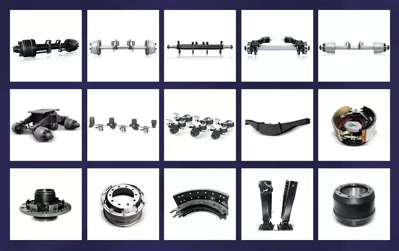
An axle is a rod or shaft that connects to the drive wheels
An axle is a rod or shaft that is fixed to the drive wheels of a vehicle. It provides support and rotates with the wheels. Generally, a vehicle has two axles. However, larger vehicles can have more. The type of axle used will depend on how much torque and speed the wheels need to travel.
Drive axles are crucial to the operation of a car. They transfer power from the engine to the wheels, so they must be strong and durable. They also need to be able to support the weight of the vehicle and resist accelerated forces. The drive axle is usually connected to a driveshaft, which extends upward into the transmission and connects with the engine.
There are two main types of axles: front wheel drive (FWD) and rear wheel drive (RWD). The former type is common in passenger vehicles, while the latter type is more common for trucks and cars. The rear wheel drive (RWD) axle connects to the drive wheels, while the front-wheel drive (FWD) axle transfers power from the transaxle differential to the wheels.
Modern drive axles consist of short rods with a flexible rubber boot covering the CV joint. The rubber boot helps to prevent dirt and grease from getting into the CV joint. The increased complexity of the drive axle increases the risk that something goes wrong with it. However, this increases the car’s traction, ride quality, and handling.
A car’s axles are designed by engineers to be extremely strong. They must be able to withstand thousands of pounds of weight, while operating under high levels of friction. But no drive axle is invincible; they will break if the vehicle is overloaded or too heavy.
The rear axle is connected to the engine and rotates with the wheels. The front axle helps with steering and absorbs road shocks. Typically, this part is made of carbon steel and nickel steel.
It absorbs braking and acceleration forces
The Axle is an important part of a vehicle’s suspension. It is responsible for absorbing braking and acceleration forces. Axle roll centres are located on the transversal vertical plane, through the center of each wheel. This is the point at which lateral force applied to the sprung mass is transferred to the unsprung mass, a process known as transfer of momentum. This force coupling point is also known as the Neutral Roll Axis.
An axle’s role in a vehicle goes beyond absorbing braking and acceleration forces. It also serves as a weight transfer device, reducing the stress on the joints of a vehicle. Its design has evolved over time to meet a variety of requirements. It must be durable and able to absorb braking and acceleration forces, while providing the right amount of structural support.
A potential diagram can be used to benchmark tyre performance. The data entered can include suspension geometry and load distributions. The lateral force potential of a tyre is calculated for each individual tyre in an axle, and the values obtained for a constant steer angle are also included.
Optimal energy recovery is crucial for absorbing braking forces and meeting the total braking force required for a given deceleration. Figure 11 shows the braking forces for the front and rear axles over a certain range when j/g = m. The thick solid line ab represents this range.
In addition to braking and acceleration forces, an axle’s lateral force capacity is limited by lateral load transfer. If one axle fails to absorb lateral forces, it might break loose and skid before the other. This can lead to understeer and oversteer. This is why it is not a good idea to put unsprung weight on a vehicle’s axle.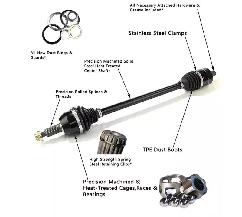
It transmits power from the engine to the wheels
The axle is an integral part of a vehicle’s drive system. It transmits power from the engine to the wheels. Different types of axles have different roles in transmission of power from the engine to the wheels. The drive shaft is the main component of an axle, connecting the engine and the wheels.
A vehicle’s axle transmits power from the engine to the rear wheels. The power is transferred through the gears to move the car forward. The inner wheel of a bicycle pedal powers the back wheel, while the outer wheel moves at a different speed. Similarly, the power from the engine is transmitted to the wheels by a car’s crankshaft and driveshaft.
The type of axle you choose depends on the size of the vehicle and its purpose. Standard axles are suitable for most vehicles, while customized axles are best suited for high-performance vehicles. Customized axles give you more control over the wheel speed and torque. It’s important to know about the types and sizes of axles to choose the right one for your vehicle.
A differential is another vital component of the drivetrain. It allows the power from the engine to reach both wheels, which allows the vehicle to accelerate and decelerate. A differential also compensates for the difference in tyre speeds on curved roads. By using a differential, you can increase the speed of the wheels and improve your car’s handling.
The differential between the front and rear axles is called a bevel ring gear. Its input shaft is supported by a ball race mounted in the axle casing. The other part of the differential is called the input helical gear. The two sun gears are connected by cross-pins.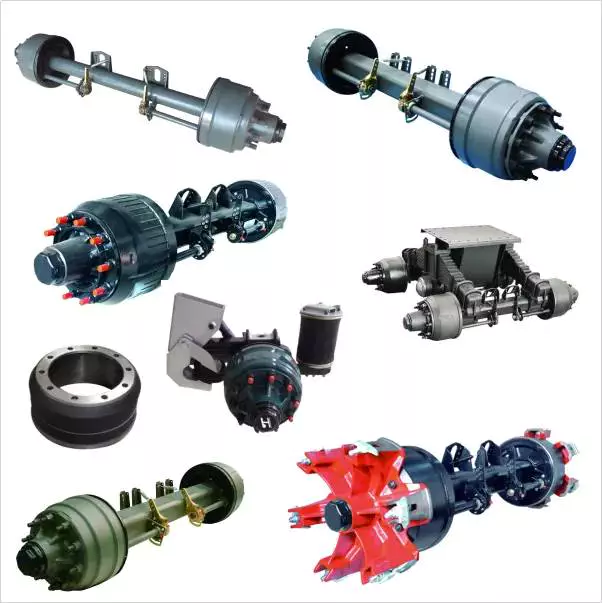
It is a simple machine for amplifying force
A simple machine is one that increases the output of force without altering the input force. For example, a lever increases force but does not create new energy. Therefore, it is necessary to balance the work input and output. It is important to keep in mind that friction can reduce energy.
Using a simple machine, you can perform various tasks. For example, you can use it to cut and pry apart objects. This type of machine involves a wheel and an axle, which have a smaller radius than the wedge. The force applied by the wheel pushes the two pieces apart.
Another simple machine that amplifies force is a gearbox. The earliest gearboxes were used to lift buckets or weights from wells. The large gear is attached to a smaller one by a hinge. The smaller gear increases the force of the larger one, allowing the small gear to lift much larger loads.
A wheel and axle is a simple machine that uses mechanical advantage to change force. A wheel is a circular disk, and an axle is a rod through the center. The mechanical advantage is a result of the combination of torque and angular momentum to work against the force of gravity. In addition, this machine is closely related to gears.
Simple machines are a great way to compare the magnitude of forces, as they use similar mechanisms. One of the oldest examples of a simple machine is a wheel and axle. A wheel is fixed to an axle, and the axle is fixed to a vertical surface. The force generated by the wheel will be proportional to the distance between the two spools.
Another simple machine that amplifies force is a lever. A lever uses a beam or a rigid rod that can pivot on its fulcrum. It is an effective tool for shifting heavy loads, and also for applying force. It also reduces the friction of a vehicle while preserving its momentum.

editor by czh 2022-12-13
China GJF Auto Drive Shaft Drive Axle for Mercedes-Benz R350 251 2006-2009 C-Me002-8h axle alignment
Product Description
Product Description
1.We are manufacturer of cv drive shaft,cv axle, cv joint and cv boot, we have more than 20-years experience in producing and selling auto parts.
2.We have strict quality control, the quality of our products is very good.
3.We are professional in different market around the world.
4.The reviews our customers given us are very positive, we have confidence in our products.
5.OEM/ODM is available, meet your requirements well.
6.Large warehouse, huge stocks!!! friendly for those customers who want small quantity.
7.Ship products out very fastly, we have stock.
| Product Name | Drive shaft | Material | 42CrMo alloy steel |
| Car fitment | Benz | Warranty | 12 months |
| Model | R350/L 251 | Place of origin | ZHangZhoug, China |
| Productive year | 2006-2009 | MOQ | 4 PCS |
| OE number | 2513301901 | Delivery time | 1-7 days |
| OEM/ODM | Yes | Brand | GJF |
| Packing size | 82*23.5*23.5 | Payment | L/C,T/T,western Union,Cash,PayPal |
| Sample service | Depends on the situation of stock | Weight | 8.3KG |
Detailed Photos
Customer Review
Packaging & Shipping
FAQ
|
US $46.8-55 / Piece | |
4 Pieces (Min. Order) |
###
| After-sales Service: | 12 Months |
|---|---|
| Condition: | New |
| Axle Number: | 1 |
| Application: | Car |
| Certification: | ASTM, CE, DIN, ISO |
| Material: | Alloy |
###
| Samples: |
US$ 35/Piece
1 Piece(Min.Order) |
|---|
###
| Customization: |
Available
|
|---|
###
| Product Name | Drive shaft | Material | 42CrMo alloy steel |
| Car fitment | Benz | Warranty | 12 months |
| Model | R350/L 251 | Place of origin | Zhejiang, China |
| Productive year | 2006-2009 | MOQ | 4 PCS |
| OE number | 2513301901 | Delivery time | 1-7 days |
| OEM/ODM | Yes | Brand | GJF |
| Packing size | 82*23.5*23.5 | Payment | L/C,T/T,western Union,Cash,PayPal |
| Sample service | Depends on the situation of stock | Weight | 8.3KG |
|
US $46.8-55 / Piece | |
4 Pieces (Min. Order) |
###
| After-sales Service: | 12 Months |
|---|---|
| Condition: | New |
| Axle Number: | 1 |
| Application: | Car |
| Certification: | ASTM, CE, DIN, ISO |
| Material: | Alloy |
###
| Samples: |
US$ 35/Piece
1 Piece(Min.Order) |
|---|
###
| Customization: |
Available
|
|---|
###
| Product Name | Drive shaft | Material | 42CrMo alloy steel |
| Car fitment | Benz | Warranty | 12 months |
| Model | R350/L 251 | Place of origin | Zhejiang, China |
| Productive year | 2006-2009 | MOQ | 4 PCS |
| OE number | 2513301901 | Delivery time | 1-7 days |
| OEM/ODM | Yes | Brand | GJF |
| Packing size | 82*23.5*23.5 | Payment | L/C,T/T,western Union,Cash,PayPal |
| Sample service | Depends on the situation of stock | Weight | 8.3KG |
What Is an Axle?
An axle is the central shaft of a rotating wheel or gear. It can be fixed to the wheels and vehicle or may rotate freely. In many cases, the axle also includes a bearing. It is a critical part of your vehicle because it is responsible for the steering and acceleration of your vehicle. Several different types of axles are available.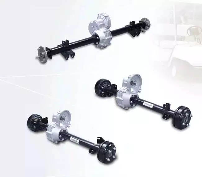
Types of axles
Axles are used in various kinds of vehicles. Each type of axle carries a different load. The first kind is called the floating axle, while the second type is called the fixed axle. Both types are commonly used in light-duty vehicles and medium-duty trucks. In addition, there are different types of semi-floating axles. These axles are mainly used in trucks, light-duty pickups, and big SUVs.
A live axle transmits power from an engine to the wheels, while a dead axle does not convey power. A dead axle is also known as a lazy axle. A number of vehicles are fitted with dead axles. These axles are usually installed in front of the driving axle. However, a pusher axle is also a dead axle.
Besides being important for vehicle movement, axles are also important for suspension. These parts transfer the driving torque from the driveshaft to the wheels, which maintains the position of the wheels. They are made of durable steel, and are very hard to bend except in cases of severe impact. There are different types of axles based on their purpose: driving axles transfer engine torque to the wheels and dead axles serve as suspension components.
Floating axles have two deep groove ball bearings at each end, and are often called full floating axles. They are usually mounted in SUVs, and are more durable than regular car axles. They are also relatively inexpensive, and can support large loads. The full floating axle is usually used in heavy-duty trucks, midsize trucks, and four-wheel-drive vehicles.
Another type of axle is called a lift axle. These axles are used in Multi-Axle Vehicles, which have more than four axles. As a result, the vehicle has a greater weight capacity than a normal car. A five-axle truck has a gross vehicle weight of forty-two tons, while its kerb weight is twelve tons. Unloaded, it is therefore equal to 30 tons.
Front axles: The front axles of cars are primarily responsible for steering and processing road shocks. The front axle is made of steel that is 0.4-3% carbon steel and one-to-three percent nickel steel. Its circular or elliptical ends and I-section center help it withstand bending loads during braking. The rear axles are the drive shafts and transmit power from the differential to the rear wheels.
Rear axles are inexpensive. They connect the rear differential and can be purchased for about $150, depending on the make and model of the car. They can be found in many modern vehicles, and are commonly found in front-drive vehicles. These modern vehicles also have axle CV shafts, which are more unique than traditional axles.
In addition to tyres, the axles are responsible for transferring power from the engine to the wheels. An axle can break due to improper maintenance or a car accident, and can affect the performance of a vehicle. A damaged axle will cause it to transfer power slowly. It might also make a clunking or sputtering noise.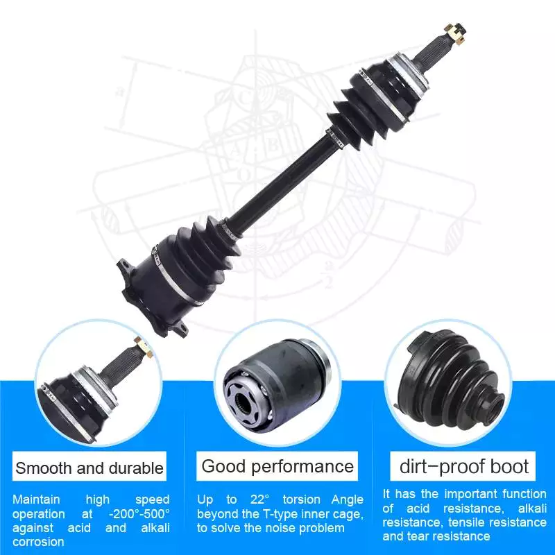
Cost of replacing an axle
Replacing an axle can be a costly task. A car’s axles should last between 35k and 100k miles. However, they can be damaged by hard hits or collisions. Depending on the extent of damage, the car may require a new axle or repair. The cost of an axle repair or replacement depends on several factors, including where the car was hit, the type of car and labor charges.
The cost of replacing an axle can range from around $200 to $900, depending on your vehicle and the type of work involved. Parts can be purchased for under $100 each, but you’ll also need to factor in labor, which can cost up to $200 or more. If you’re replacing both the rear and front axles, the cost will be higher than for just one axle replacement.
Axle repair is a complicated procedure, and the cost varies based on the make and model of your vehicle. A replacement axle will allow wheels to rotate freely. Depending on the severity of the problem, a front axle repair can run between $500 and $800. A rear axle repair will run you about $700.
Although an axle replacement may seem like an expensive and time-consuming task, the process will be less expensive than repairing the whole assembly. Professional mechanics can also replace one axle at a time. If you have a warranty on your car, this can cover the cost of the repair. This is a good way to save money and time while getting your car back on the road.
One of the most common causes of axle failure is the leakage of grease. When grease leaks, the CV joint is left dry, and dirt will get in. Without lubrication, this leads to increased wear, and increases the cost of axle replacement. For this reason, most mechanics will recommend replacing the entire half-shaft instead of just the axle, thereby reducing the cost and the labor time.
Depending on the severity of the damage, replacing an axle can take several hours. Aside from the repair, an alignment may be needed afterward. Most garages include this service with axle work. Depending on the type of alignment, it could cost from $20 to $150+. A complete diagnosis of the vehicle can take up to three hours to complete.
In some cases, a broken axle is completely irreparable. It will damage the rest of the vehicle and may lead to other problems. In such cases, it’s best to take it to a mechanic for repair as soon as possible. In most cases, an axle replacement should be needed just once during the life of the car.
Axles are available in pairs or individually. You can also find them at a junkyard. Installing a new axle is not difficult if you have the proper tools. An impact wrench can help make the job go faster. However, it’s important to have a flat surface for the work and wear safety gear.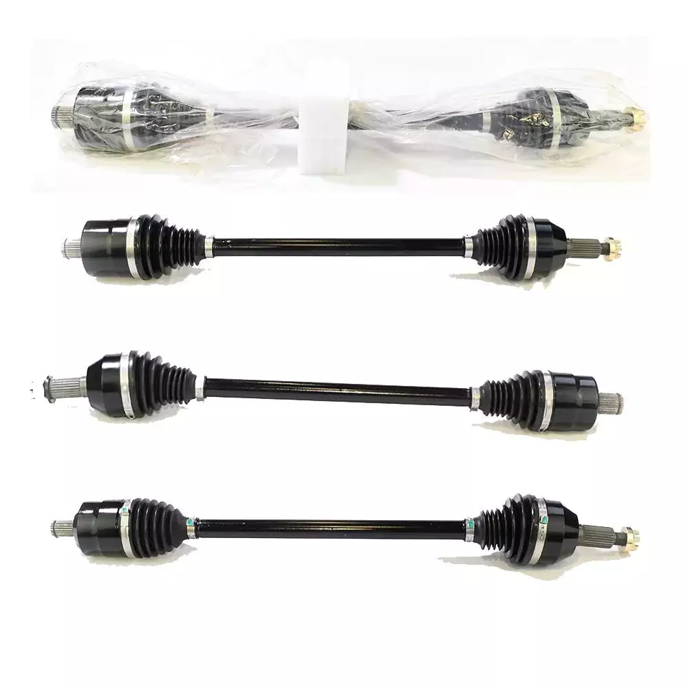
Insurance coverage for repairing an axle
Car insurance may cover the costs of repairing an axle if it’s damaged in an accident, but if the damage occurred because of normal wear and tear, it may not be covered. Similarly, your insurance policy may not cover damage to tires or rims, and it might not cover the costs of a new axle, depending on the condition of the axle.
Your car’s axle is an important part of the vehicle, transferring power from the engine to the wheels. They are built to be durable, but they can bend or break due to a variety of factors, including running over a curb, hitting potholes at high speed, and auto collisions. In such cases, your car may not be able to drive, and a replacement axle may be expensive.
Some of the symptoms of an axle problem are shuddering or clicking sounds when shifting gears. Occasionally, a car may even completely stop. This can lead to an accident or even a loss of control. It’s best to fix an axle before it damages your car in an accident. In some cases, repairing the axle can cost only a few hundred dollars.
You should have your vehicle inspected for signs of wear and tear before repairing an axle. It’s crucial to take your vehicle to a mechanic immediately after an accident, as delayed repairs can lead to further suspension issues. Ideally, your vehicle’s axle should last four to five years or fifty thousand miles, although these numbers can vary. The life of an axle depends on a variety of factors, including the type of driving you do and how often you drive. Driving over rocky or icy surfaces can wear out the protective rubber boot. The rubber can also dry out and crack over time.
While the axle itself is a sturdy component, the parts connected to it are more susceptible to wear and tear. Associated components such as axle bearings are critical to the axle, as they help control the speed of the wheels when they turn. They also help maintain the integrity of the vehicle’s structural system.
Repairing an axle can be expensive, depending on the vehicle’s make and model. Depending on the severity of the problem, the costs of an axle repair can range from $500 to more than $1,000. The cost of an axle repair may also include other necessary repairs. If the damage is caused by normal use, your insurance provider may pay for the costs.
When your vehicle is in need of an axle replacement, it’s a good idea to contact a vehicle repair shop. A vehicle repair shop will give you the best possible estimate of the cost and time to repair the axle.
editor by czh 2022-12-01