Product Description
| Type: CV Joint Kit |
| Installation position: Wheel Side |
| ABS diameter: 74mm |
| Sealing ring diameter: 60mm |
| External Teeth : 38mm Internal Teeth : 27mm |
| Length: 1
514781 514787 CVJ5174.10 QVJ700 TDL4134R DRC57134K E01584002 E01584004 E30 0571 E30571 E301957 E301959 75712 75712S 21119 CV70N JCV70N VKJA5261 22591 22639 3571240 854571131 18569
|
PICS
Car Applicaition
AUDI 100 C4 Avant (4A5) 2.5 TDI
AUDI 100 C4 Avant (4A5) 2.8 E
AUDI 100 C4 Avant (4A5) 2.8 E quattro
AUDI 100 C4 Avant (4A5) S4 Turbo quattro
AUDI 100 C4 Saloon (4A2) 2.5 TDI
AUDI 100 C4 Saloon (4A2) 2.8 E
AUDI 100 C4 Saloon (4A2) 2.8 E quattro
AUDI 100 C4 Saloon (4A2) S4 V8 quattro
AUDI A6 C4 (4A2) 2.5 TDI
AUDI A6 C4 (4A2) 2.5 TD
AUDI A6 C4 (4A2) 2.5 TDI quattro
AUDI A6 C4 (4A2) 2.8
AUDI A6 C4 (4A2) 2.8 quattro
Company Profile
ZheJiang Mighty Machinery Co. Ltd is a professional manufacturer of auto bearings for more than 20 years. We provide a one-stop service for our customers. Our main products include wheel bearings & hub assembly, belt tensioners, clutch release bearings, and other parts.
Relying on the professional and rich manufacturing experience and many substantial factories which stable cooperated for many years, Mighty suppliers customers high-quality products at very competitive prices.
Customer satisfaction is our First Priority, We adhere to the concept of ” Quality First, Customer First”. We will continue to provide high-quality products and the best services to our customers and build up CHINAMFG long-time friendship partners.
Our Advantage
More than 20 years of manufacturing and exporting experience
OEM manufacturing available
Full range, large stock
Quickly feedback
One year warranty
One-stop service
On-time delivery
Packing & Shipping
FAQ
1. What‘s the minimum order quantity?
We don’t have the minimum order quantity. We can also provide free samples, but you need to pay the freight.
2. Do you provide ODM&OEM order service?
Yes, we provide ODM&OEM services to customers around the world, and we can customize different brands and different sizes of packaging boxes according to customers’ requirements.
3. After-sales service and warranty time
We guarantee that our products will be free from defects in materials and workmanship within 12 months from the date of delivery. The warranty is void due to improper use, incorrect installation, and physical damage.
4. How to place an order?
Send us an email of the models, brand, quantity, consignee information, model of transportation, and payment
Confirm payment and arrange the production.
5. What are your packing conditions?
We use standardized export packaging and environmental protection packaging materials. If you have a legally registered patent, we will package the goods in your brand box after receiving your authorization
6. What are your payment terms?
T/T is 30% of the payment in advance and 70% balance before delivery. Before you pay the balance, we will show you photos or videos of the products and packaging.
7. How long is your delivery time?
The delivery time of the sample order is 3-5 days, and that of a batch order is 5-45 days. The exact delivery time depends on the item and the quantity you ordered.
8. Do you test all products before delivery?
Yes, according to ISO standards, we have professional Q/C personnel, precision testing instruments, and an internal inspection system. We control the quality of every process from material receiving to packaging to ensure that you receive high-quality products
/* March 10, 2571 17:59:20 */!function(){function s(e,r){var a,o={};try{e&&e.split(“,”).forEach(function(e,t){e&&(a=e.match(/(.*?):(.*)$/))&&1
| After-sales Service: | One Year |
|---|---|
| Warranty: | One Year |
| Condition: | New |
| Color: | Natural Color |
| Certification: | CE, ISO |
| Structure: | Single |
| Samples: |
US$ 50/Piece
1 Piece(Min.Order) | |
|---|
| Customization: |
Available
| Customized Request |
|---|

How do you ensure proper alignment when connecting a universal joint?
Ensuring proper alignment when connecting a universal joint is essential for its optimal performance and longevity. Here’s a detailed explanation:
Proper alignment of a universal joint involves aligning the input and output shafts to minimize angular misalignment and maintain a smooth and efficient power transfer. Here are the steps to ensure proper alignment:
- Measure shaft angles: Begin by measuring the angles of the input and output shafts that the universal joint will connect. This can be done using a protractor or an angle measuring tool. The angles should be measured in relation to a common reference plane, such as the horizontal or vertical.
- Calculate the operating angle: The operating angle of the universal joint is the difference between the angles of the input and output shafts. This angle determines the amount of angular misalignment that the universal joint needs to accommodate. It is crucial to calculate the operating angle accurately to ensure the proper selection of a universal joint suitable for the application.
- Select the appropriate universal joint: Based on the calculated operating angle, choose a universal joint that is designed to handle the specific misalignment requirements. Universal joints come in various sizes and designs to accommodate different operating angles and torque loads. Refer to the manufacturer’s specifications and guidelines to select the appropriate universal joint for the application.
- Achieve parallel alignment: To ensure proper alignment, it is important to align the input and output shafts so that they are parallel to each other when viewed from the common reference plane. This can be achieved by adjusting the mounting positions of the shafts or using alignment tools such as straightedges or laser alignment systems. The goal is to minimize any offset or skew between the shafts.
- Check centerline alignment: Once the shafts are parallel, it is necessary to check the centerline alignment. This involves verifying that the centerline of the input shaft and the centerline of the output shaft are in line with each other. Misalignment in the centerline can result in additional stress on the universal joint and lead to premature wear or failure. Use measurement tools or visual inspection to ensure the centerline alignment is maintained.
- Securely fasten the universal joint: After achieving proper alignment, securely fasten the universal joint to the input and output shafts according to the manufacturer’s recommendations. Follow the specified torque values for the fasteners to ensure proper clamping force without over-tightening. This will help maintain the alignment during operation.
- Perform regular maintenance: To ensure continued proper alignment, it is important to perform regular maintenance, including periodic inspections and lubrication of the universal joint. Regular maintenance can help detect any misalignment or wear issues early on and prevent further damage or failure.
By following these steps and paying attention to proper alignment, the universal joint can operate smoothly and effectively, minimizing stress, wear, and the risk of premature failure.
In summary, ensuring proper alignment when connecting a universal joint involves measuring shaft angles, calculating the operating angle, selecting the appropriate universal joint, achieving parallel alignment, checking centerline alignment, securely fastening the joint, and performing regular maintenance.

How does a universal joint affect the overall efficiency of a system?
A universal joint can have an impact on the overall efficiency of a system in several ways. The efficiency of a system refers to its ability to convert input power into useful output power while minimizing losses. Here are some factors that can influence the efficiency of a system when using a universal joint:
- Friction and energy losses: Universal joints introduce friction between their components, such as the cross, bearings, and yokes. This friction results in energy losses in the form of heat, which reduces the overall efficiency of the system. Proper lubrication and maintenance of the universal joint can help minimize friction and associated energy losses.
- Angular misalignment: Universal joints are commonly used to transmit torque between non-aligned or angularly displaced shafts. However, when the input and output shafts are misaligned, it can lead to increased angular deflection, resulting in energy losses due to increased friction and wear. The greater the misalignment, the higher the energy losses, which can affect the overall efficiency of the system.
- Backlash and play: Universal joints can have inherent backlash and play, which refers to the amount of rotational movement that occurs before the joint begins to transmit torque. Backlash and play can lead to decreased efficiency in applications that require precise positioning or motion control. The presence of backlash can cause inefficiencies, especially when reversing rotational direction or during rapid changes in torque direction.
- Mechanical vibrations: Universal joints can generate mechanical vibrations during operation. These vibrations can result from factors such as angular misalignment, imbalance, or variations in joint geometry. Mechanical vibrations not only reduce the efficiency of the system but can also contribute to increased wear, fatigue, and potential failure of the joint or other system components. Vibration damping techniques, proper balancing, and maintenance can help mitigate the negative effects of vibrations on system efficiency.
- Operating speed: The operating speed of a system can also impact the efficiency of a universal joint. At high rotational speeds, the limitations of the joint’s design, such as imbalance, increased friction, or decreased precision, can become more pronounced, leading to reduced efficiency. It’s important to consider the specific speed capabilities and limitations of the universal joint to ensure optimal system efficiency.
Overall, while universal joints are widely used and provide flexibility in transmitting torque between non-aligned shafts, their design characteristics and operational considerations can affect the efficiency of a system. Proper maintenance, lubrication, alignment, and consideration of factors such as misalignment, backlash, vibrations, and operating speed contribute to maximizing the efficiency of the system when utilizing a universal joint.

Are there different types of universal joints available?
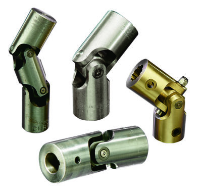
Yes, there are different types of universal joints available to suit various applications and requirements. Let’s explore some of the commonly used types:
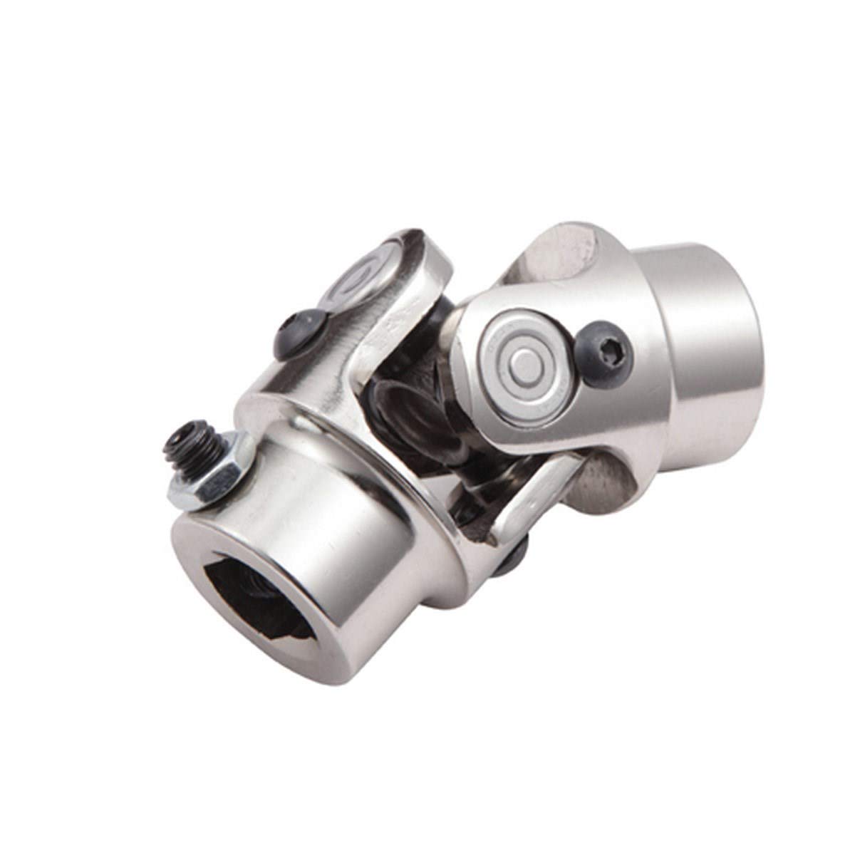
- Single Joint (Cardan Joint): The single joint, also known as a Cardan joint, is the most basic and widely used type of universal joint. It consists of two yokes connected by a cross-shaped center piece. The yokes are typically 90 degrees out of phase with each other, allowing for angular displacement and misalignment between shafts. Single joints are commonly used in automotive drivelines and industrial applications.
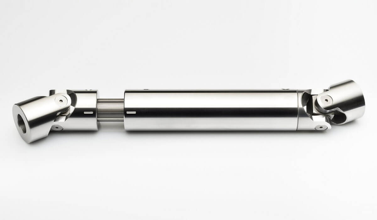
- Double Joint: A double joint, also referred to as a double Cardan joint or a constant velocity joint, is an advanced version of the single joint. It consists of two single joints connected in series with an intermediate shaft in between. The use of two joints in series helps to cancel out the velocity fluctuations and reduce vibration caused by the single joint. Double joints are commonly used in automotive applications, especially in front-wheel-drive vehicles, to provide constant velocity power transmission.
- Tracta Joint: The Tracta joint, also known as a tripod joint or a three-roller joint, is a specialized type of universal joint. It consists of three rollers or balls mounted on a spider-shaped center piece. The rollers are housed in a three-lobed cup, allowing for flexibility and articulation. Tracta joints are commonly used in automotive applications, particularly in front-wheel-drive systems, to accommodate high-speed rotation and transmit torque smoothly.
- Rzeppa Joint: The Rzeppa joint is another type of constant velocity joint commonly used in automotive applications. It features six balls positioned in grooves on a central sphere. The balls are held in place by an outer housing with an inner race. Rzeppa joints provide smooth power transmission and reduced vibration, making them suitable for applications where constant velocity is required, such as drive axles in vehicles.
- Thompson Coupling: The Thompson coupling, also known as a tripodal joint, is a specialized type of universal joint. It consists of three interconnected rods with spherical ends. The arrangement allows for flexibility and misalignment compensation. Thompson couplings are often used in applications where high torque transmission is required, such as industrial machinery and power transmission systems.
These are just a few examples of the different types of universal joints available. Each type has its own advantages and is suitable for specific applications based on factors such as torque requirements, speed, angular displacement, and vibration reduction. The selection of the appropriate type of universal joint depends on the specific needs of the application.


editor by CX 2024-01-11