Product Description
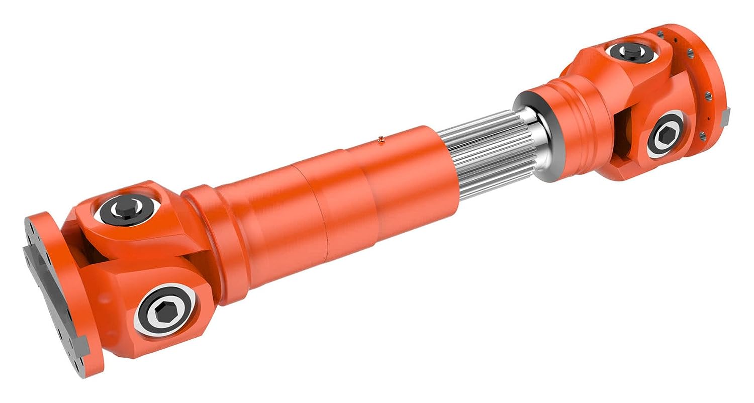
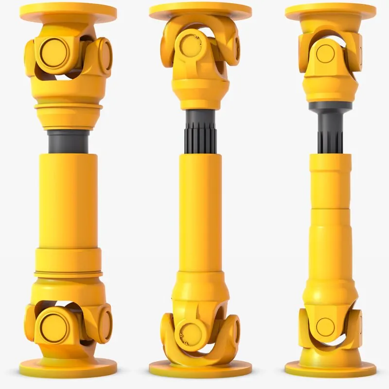
Zinc alloy cardan joint with U shape head,work with TF handle:
| Type: | RS-UJ03 |
| Length: | 350mm,we could produce the length as per request. |
| Material: | Zinc alloy |
| Color: | Silver |
CHINAMFG shutter component Co.,Ltd estabalised in 2012, is a professional roller shutter component manufacturer specialized in innovation,developing,designing and producing all kinds of the roller shutter,roller door,garage door,awnings,roller blinds accessories and other related products for manual and motorized system.
Main products like aluminium side frame,cover box,handles,cardan joint,plastic and metal caps,galvanized tube,crank wheel,coiler,switch also the complete roller shutter set.
Our workshop line introduced advanced technology, imported advanced equipment,with the plastic injection machine,aluminium die casting machine,galvanized
tube machine and punching machine.all products with high quality and competitive price.
Employs experienced technical and management personnel,features high technical capabilities and strictly quality control procedures.
Goods sell well in Europe,Middle east,Australia,North and South America market with good reputation.
We located in HangZhou,China,an important economic hub and port city
,convenient for sea and air transportation from HangZhou or ZheJiang .
Which is a a fast-growing city.as well the center of the mechanical and electronic industry,has the big advantage for the home automation system.
With the efforts and supports of all our employees, we will do our best to provide our customers with more high-quality products and more efficient service.
We stick to the principle of “quality first, service first, continuous improvement and innovation to meet the customers” for the management and “zero defect, zero complaints” as the quality objective.
Our mission is “Integrity and innovation are the soul and spirit.”
Welcome to visit us CHINAMFG shutter component!
/* March 10, 2571 17:59:20 */!function(){function s(e,r){var a,o={};try{e&&e.split(“,”).forEach(function(e,t){e&&(a=e.match(/(.*?):(.*)$/))&&1
| Kind: | Roller Shutter Accessories |
|---|---|
| Structure: | Vertical |
| Open Type: | Manual |
| Samples: |
US$ 4/Piece
1 Piece(Min.Order) | Order Sample |
|---|
| Customization: |
Available
| Customized Request |
|---|
.shipping-cost-tm .tm-status-off{background: none;padding:0;color: #1470cc}
|
Shipping Cost:
Estimated freight per unit. |
about shipping cost and estimated delivery time. |
|---|
| Payment Method: |
|
|---|---|
|
Initial Payment Full Payment |
| Currency: | US$ |
|---|
| Return&refunds: | You can apply for a refund up to 30 days after receipt of the products. |
|---|

How do you calculate the operating angles of a cardan joint?
The operating angles of a cardan joint can be calculated based on the angular misalignment between the input and output shafts. The operating angles are crucial for determining the joint’s performance and ensuring its proper functioning. Here’s a detailed explanation of how to calculate the operating angles of a cardan joint:
- Identify the Shaft Axes: Begin by identifying the axes of the input and output shafts connected by the cardan joint. These axes represent the rotational axes of the shafts.
- Measure the Angular Misalignments: Measure the angular misalignments between the shaft axes. The misalignments are typically measured in terms of angles, such as angular displacement in degrees or radians. There are three types of misalignments to consider:
- Angular Misalignment (α): This refers to the angular difference between the two shaft axes in the horizontal plane (X-Y plane).
- Parallel Misalignment (β): Parallel misalignment represents the offset or displacement between the two shaft axes in the vertical plane (Z-axis).
- Axial Misalignment (γ): Axial misalignment refers to the shift or displacement of one shaft along its axis with respect to the other shaft.
- Calculate the Operating Angles: Once the misalignments are measured, the operating angles can be calculated using trigonometric functions. The operating angles are:
- Operating Angle (θ): The operating angle is the total angular misalignment between the input and output shafts. It is calculated as the square root of the sum of the squares of the individual misalignments:
These calculated operating angles provide valuable information about the misalignment and geometry of the cardan joint. They help in selecting the appropriate joint size, determining the joint’s torque capacity, assessing potential operating issues, and ensuring proper installation and alignment of the joint within the system.
It is important to note that these calculations assume small operating angles and neglect any elastic deformation or non-linearities that may occur in the joint. In cases where larger operating angles or more precise calculations are required, advanced engineering techniques or software tools specific to cardan joint analysis may be employed.

Can cardan joints be used in industrial machinery and manufacturing?
Yes, cardan joints are commonly used in industrial machinery and manufacturing applications due to their versatility, durability, and ability to transmit torque at various angles. They offer several advantages that make them suitable for a wide range of industrial applications. Here’s a detailed explanation:
1. Torque Transmission: Industrial machinery often requires the transmission of torque between different components or shafts that may not be in a perfectly aligned position. Cardan joints excel at transmitting torque even at significant angles and misalignments, allowing for flexible power transmission in industrial applications. They can efficiently transfer high torque loads and handle varying operating conditions.
2. Misalignment Compensation: Cardan joints are designed to accommodate misalignments and angular variations, making them ideal for industrial machinery. They can compensate for misalignments caused by structural deflection, thermal expansion, or other factors, ensuring smooth and reliable power transmission. This capability helps to minimize stress and wear on connected components and extends the life of the machinery.
3. Flexibility and Articulation: Industrial machinery often requires flexibility and articulation to adapt to different production processes or accommodate dynamic movements. Cardan joints provide rotational freedom and allow for angular movement, enabling the machinery to adjust to changing requirements. Their universal joint design allows for smooth rotation and accommodates the required range of motion.
4. Compact Design: Cardan joints have a relatively compact design, making them suitable for integration into industrial machinery where space is often limited. Their compact size allows for efficient packaging within the machinery, optimizing overall design and minimizing footprint. This is especially beneficial in applications where multiple joints are required within a confined space.
5. Durability and Strength: Industrial machinery operates under demanding conditions, including heavy loads, high speeds, and harsh environments. Cardan joints are often constructed using durable materials such as alloy steels or high-strength alloys, providing the necessary strength and resilience to withstand industrial applications. They are designed to handle the demanding loads and forces encountered in manufacturing processes.
6. Easy Maintenance and Serviceability: Cardan joints are generally low-maintenance components. They require periodic inspection, lubrication, and replacement of worn parts, but their design often allows for easy access and replacement if needed. This facilitates maintenance activities and minimizes downtime in industrial machinery.
7. Versatility: Cardan joints are available in various configurations, sizes, and load capacities, allowing them to be tailored to specific industrial machinery requirements. They can be customized to accommodate different shaft sizes, torque ratings, and mounting arrangements, making them adaptable to a wide range of manufacturing applications.
8. Cost-Effectiveness: Cardan joints offer a cost-effective solution for torque transmission in industrial machinery. Their durability, reliability, and long service life contribute to reduced maintenance and replacement costs. Additionally, their ability to compensate for misalignments can help minimize wear on other machinery components, further reducing overall maintenance expenses.
When integrating cardan joints into industrial machinery and manufacturing systems, it is important to consider the specific application requirements, operating conditions, and load characteristics. Proper design, selection, and installation practices should be followed to ensure optimal performance and longevity.
Consulting with engineers or experts specializing in drivetrain systems and industrial machinery design can provide valuable insights and guidance on the selection, integration, and maintenance of cardan joints for specific industrial applications.

What is a cardan joint and how does it work?
A cardan joint, also known as a universal joint or U-joint, is a mechanical coupling used to transmit rotational motion between two shafts that are not collinear or have a constant angular relationship. It provides flexibility and accommodates misalignment between the shafts. Here’s a detailed explanation of how a cardan joint works:
A cardan joint consists of three main components: two yokes and a cross-shaped member called the cross or spider. The yokes are attached to the ends of the shafts that need to be connected, while the cross sits in the center, connecting the yokes.
The cross has four arms that intersect at a central point, forming a cross shape. Each arm has a bearing surface or trunnion on which the yoke of the corresponding shaft is mounted. The yokes are typically fork-shaped and have holes or bearings to accommodate the trunnions of the cross.
When the input shaft rotates, it transfers the rotational motion to one of the yokes. The cross, being connected to both yokes, transmits this motion to the other yoke and subsequently to the output shaft.
The key feature of a cardan joint is its ability to accommodate misalignment between the input and output shafts. This misalignment can be angular, axial, or both. As the input and output shafts are not collinear, the angles between the shafts cause the yokes to rotate at different speeds during operation.
The universal joint’s design allows the cross to rotate freely within the yokes, while still transferring motion from one shaft to the other. When the input shaft rotates, the yoke connected to it rotates with the shaft. This rotation causes the cross to tilt, as the other yoke is fixed to the output shaft. As a result, the angle between the arms of the cross changes, allowing for the compensation of misalignment.
As the cross tilts, the relative speeds of the yokes change, but the rotational motion is still transferred to the output shaft. The cardan joint effectively converts the input shaft’s rotation into a modified rotation at the output shaft, accommodating the misalignment between the two shafts.
It’s important to note that while cardan joints provide flexibility and can handle misalignment, they introduce certain limitations. These include non-uniform motion, increased vibration, backlash, and potential loss of efficiency at extreme operating angles. Regular maintenance, proper lubrication, and adherence to manufacturer guidelines are essential to ensure the optimal performance and longevity of cardan joints.


editor by CX 2024-02-06