Product Description
Universal Joint Cross
Basic Info.
| Model NO. | GE 55 SX | Separated | Separated |
| MOQ | 1PCS | Quality | Guaranteed |
| Mainly Market | America Europe Asia Africa | Serive | OEM |
| Stock | Rich Stocks | Feature | High Precision, Small Torque, Low Noise |
| Transport Package | Industrial Packing or as Per Requirement | Specification | GE 55 SX |
| Trademark | FOS Bearing or OEM | Origin | YANDIAN, ZheJiang |
| HS Code | 8482200000 | Production Capacity | 7000PCS/Month |
Universal Joint Cross
Product Serie
Universal Joint Cross
Production Process
Production Process
Inspection
Our Advantage
Package and shipment
Company Profile
HangZhou Siruibo Bearing Technology Co., Ltd. is a company mainly engaged in manufacturing and selling outer spherical bearings. The registered capital is Five million.
Since its establishment 20 years ago, the company is committed to Mounted Bearing Unit (maintenance-free bearings, engraving machine bearings, holding machine shaft Bearing, no-tillage machine bearing, fan bearing, high temperature bearing, zinc alloy bearing, food grade bearing unit) research and development. With the most complete varieties and best advanced manufacturing technology in production of Mounted Bearing Unit, to be a reliable enterprises, we welcome your cooperation. Currently, our company produce 10 series of more than 260 varieties of outer spherical bearings and 13 different structural categories of outer spherical bearing special seats, all adopted International standard design and manufacturing. Registered trademark “FOS” .
Through the efforts and unremitting pursuit of all employees of the company, all products accepted by international standards. Over the years of Expansion and technical transformation, we developed into a Mounted Bearing Unit with large scale of professional manufacturers, for the bearing industry in China, has made a contribution to the development of Bearing.
HangZhou Siruibo Bearing Technology Co., Ltd. has a production capacity of 1 million sets/year, with an annual output value of 30 million yuan. We produce 30 varieties monthly , with 45-60 days lead time.
The company has a perfect material and product quality inspection equipment, according to the strict scientific Quality assurance system, to prove satisfactory to our customers. Our products widely used in agricultural Industry machinery, textile machinery and light industry, chemical industry, metallurgy, printing, food, transportation, coal, packaging and other industries and the introduction of machinery .Our products have exported to Europe, America and many countries and regions in South east Asia.
Exhibitions
About us:
We are 1 manufactuer of bearing for more than 20 years.
Give us a chance, we will cooperate with our passion.
Our professional, reliable, experienced products and service can meet your request.
Why choose us?
SAMPLES
1. Samples quantity: 1-10 PCS are available.
2. Free samples: It depends on the Model No., material and quantity. Some of the bearings samples need client to pay samples charge and shipping cost.
3. It’s better to start your order with Trade Assurance to get full protection for your samples order.
CUSTOMIZED
The customized LOGO or drawing is acceptable for us.
MOQ
1. MOQ: 10 PCS mix different standard bearings.
2. MOQ: 3000 PCS customized your brand bearings.
OEM POLICY
1. We can printing your brand (logo, artwork)on the shield or laser engraving your brand on the shield.
2. We can custom your packaging according to your design
3. All copyright own by clients and we promised don’t disclose any info.
SUPORT
Please visit our bearings website, we strongly encourge that you can communicate with us through email, thanks!
We have all kinds of bearings, just tell me your item number and quantity, best price will be offered to you soon
The material of the bearings, precision rating, seals type, OEM service, etc, all of them we can make according to your requirement.
/* March 10, 2571 17:59:20 */!function(){function s(e,r){var a,o={};try{e&&e.split(“,”).forEach(function(e,t){e&&(a=e.match(/(.*?):(.*)$/))&&1
| Contact Angle: | 15° |
|---|---|
| Aligning: | Non-Aligning Bearing |
| Separated: | Unseparated |
| Rows Number: | Single |
| Load Direction: | Radial Bearing |
| Material: | Bearing Steel |
| Samples: |
US$ 1/Piece
1 Piece(Min.Order) | |
|---|
| Customization: |
Available
| Customized Request |
|---|
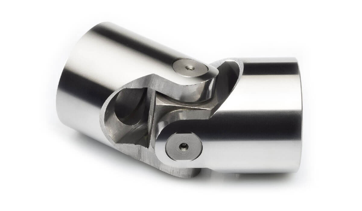
What are the potential challenges in designing and manufacturing universal joints?
Designing and manufacturing universal joints can present various challenges that need to be addressed to ensure optimal performance and reliability. Here’s a detailed explanation:
1. Misalignment Compensation: Universal joints are primarily designed to accommodate angular misalignment between two shafts. Designing a universal joint that can effectively compensate for misalignment while maintaining smooth power transmission can be challenging. The joint must provide flexibility without sacrificing strength or introducing excessive play, which could lead to vibration, noise, or premature wear.
2. Torque Transmission: Universal joints are often used in applications that require the transfer of high torque loads. Designing the joint to handle these loads without failure or excessive wear is a significant challenge. The selection of appropriate materials, heat treatment processes, and bearing designs becomes crucial to ensure the strength, durability, and reliability of the joint.
3. Lubrication and Sealing: Universal joints require proper lubrication to minimize friction, heat generation, and wear between the moving components. Designing an effective lubrication system that ensures sufficient lubricant supply to all critical areas can be challenging. Additionally, designing seals and protective covers to prevent contamination and retain lubrication presents a challenge, as the joint must maintain flexibility while ensuring adequate sealing.
4. Bearing Design and Wear: Universal joints rely on bearings to facilitate smooth rotation and to support the shafts. Designing the bearing arrangement to withstand the loads, maintain proper alignment, and resist wear is essential. Choosing the appropriate bearing type, such as needle bearings or plain bearings, and optimizing their size, material, and lubrication conditions are key challenges in the design process.
5. Manufacturability: Manufacturing universal joints with precision and consistency can be challenging due to their complex geometries and the need for tight tolerances. The manufacturing process must ensure accurate machining, assembly, and balancing of the joint components to achieve proper fit, alignment, and balance. Specialized machining techniques and quality control measures are often required to meet the desired specifications.
6. Cost and Size Optimization: Designing universal joints that are cost-effective and compact while meeting performance requirements can be a challenging task. Balancing the need for robustness, durability, and material efficiency with cost considerations requires careful engineering and optimization. Designers must strike a balance between performance, weight, space constraints, and manufacturing costs to create an efficient and economical universal joint.
7. Application-Specific Considerations: Designing universal joints for specific applications may introduce additional challenges. Factors such as environmental conditions, temperature extremes, exposure to corrosive substances, high-speed operation, or heavy-duty applications need to be carefully considered and addressed in the design and material selection process. Customization and adaptation of universal joints to meet unique application requirements can pose additional challenges.
Addressing these challenges in the design and manufacturing process requires a combination of engineering expertise, material science knowledge, advanced manufacturing techniques, and thorough testing and validation procedures. Collaboration between design engineers, manufacturing engineers, and quality control personnel is crucial to ensure the successful development and production of reliable universal joints.
In summary, the potential challenges in designing and manufacturing universal joints include misalignment compensation, torque transmission, lubrication and sealing, bearing design and wear, manufacturability, cost and size optimization, and application-specific considerations. Overcoming these challenges requires careful engineering, precision manufacturing processes, and consideration of various factors to achieve high-performance and reliable universal joints.
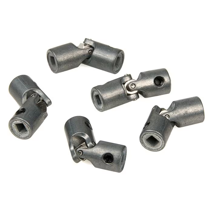
What materials are commonly used in the construction of universal joints?
Universal joints are constructed using various materials that provide strength, durability, and resistance to wear and fatigue. Here’s a detailed explanation:
The choice of materials for universal joints depends on factors such as the application, load requirements, operating conditions, and cost considerations. Here are some commonly used materials:
- Steel: Steel is one of the most common materials used in universal joint construction. Alloy steels, such as 4140 or 4340, are often employed due to their high strength, toughness, and resistance to wear and fatigue. Steel universal joints can withstand heavy loads and harsh operating conditions, making them suitable for various industrial applications.
- Stainless Steel: Stainless steel is chosen for universal joints when corrosion resistance is a critical requirement. Stainless steel alloys, such as 304 or 316, offer excellent resistance to rust, oxidation, and chemical corrosion. These joints are commonly used in applications where exposure to moisture, chemicals, or harsh environments is expected.
- Cast Iron: Cast iron is occasionally used in universal joints, particularly in older or specialized applications. Cast iron provides good strength and wear resistance, but it is generally heavier and less flexible than steel. It may be used in specific situations where its properties are advantageous, such as in large industrial machinery.
- Aluminum: Aluminum universal joints are utilized when weight reduction is a priority. Aluminum alloys offer a good balance of strength and lightweight properties. These joints are commonly found in applications where weight savings are crucial, such as aerospace, automotive, or robotics.
- Bronze: Bronze is sometimes used for bearings or bushings within universal joints. Bronze alloys provide good wear resistance, low friction, and the ability to withstand high temperatures. They are often employed in applications where self-lubricating properties and resistance to galling are required. Bronze bearings can be found in universal joints used in heavy machinery, marine equipment, or agricultural machinery.
It’s worth noting that the specific choice of materials may vary depending on the manufacturer, application requirements, and industry standards. Different combinations of materials may also be used for different components within a universal joint, such as the yokes, crosses, bearings, or seals, to optimize performance and durability.
In summary, universal joints are commonly constructed using materials such as steel, stainless steel, cast iron, aluminum, and bronze. The selection of materials depends on factors like strength, durability, wear resistance, corrosion resistance, weight considerations, and specific application requirements.
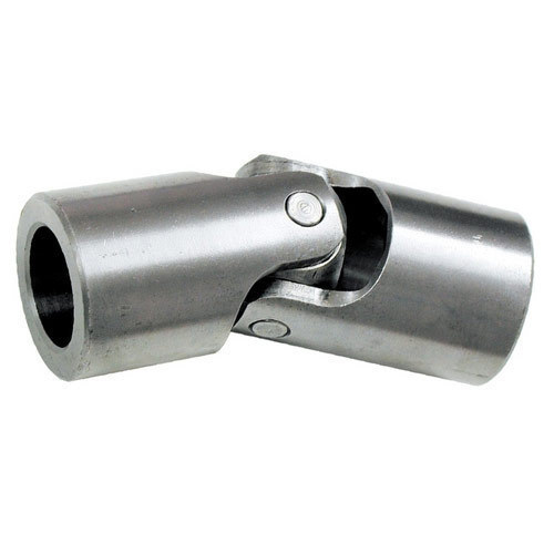
Can you explain the purpose of a universal joint in a drive shaft?
In a drive shaft, a universal joint serves a crucial purpose in transmitting rotational motion between the engine or power source and the driven wheels or other components. Let’s delve into the purpose of a universal joint in a drive shaft:
A drive shaft is a mechanical component that transfers torque from the engine or power source to the wheels or other driven components in a vehicle or machinery. It is typically used in rear-wheel drive and four-wheel drive systems. The drive shaft connects the transmission output shaft to the differential or axle assembly, allowing the wheels to receive power and propel the vehicle forward.
The purpose of a universal joint in a drive shaft is to accommodate the misalignment and changes in angles between the transmission and the differential or axle assembly. Misalignment can occur due to various factors, including the vehicle’s suspension system, the position of the engine, and the movement of the wheels. Without a flexible coupling mechanism, misalignment would cause binding, vibration, and potential damage to the drive shaft and other drivetrain components.
Universal joints provide the necessary flexibility and articulation to compensate for misalignment and changes in angles. They allow the drive shaft to bend and rotate at varying angles while transmitting torque from the transmission to the differential. The universal joint allows the drive shaft to operate smoothly and efficiently, even when the vehicle is in motion and the suspension system causes changes in the relative positions of the transmission and the differential.
When the engine or power source rotates the drive shaft, the universal joint allows angular displacement between the transmission and the differential. As the drive shaft bends and changes angles, the universal joint accommodates these movements, ensuring continuous torque transmission without placing excessive stress on the drivetrain components.
The universal joint consists of a cross-shaped or H-shaped yoke with bearings at the ends of each arm. These bearings allow for smooth rotation and minimize friction between the yoke and the drive shaft. The design of the universal joint enables it to flex and articulate, compensating for misalignment and changes in angles without affecting the rotation of the drive shaft.
Overall, the purpose of a universal joint in a drive shaft is to provide the necessary flexibility and articulation to accommodate misalignment and changes in angles. By allowing the drive shaft to bend and rotate at varying angles, the universal joint ensures smooth and efficient torque transmission between the engine and the driven wheels or components, contributing to the proper functioning of the vehicle or machinery.


editor by CX 2024-01-10
China Hot selling Assembly Cardan Shaft Gun-34 Universal Joint Cross Bearing Kit Universal Joint Cardan Joint Cross Pin Type Joint U-Joint Bearing
Product Description
Free Sample Assembly Cardan Shaft GUN-34 Universal Joint Cross Bearing Kit Universal Joint Cardan Joint Cross Pin Type Joint U-Joint Bearing
| Type | Universal Joint |
| Brand | TFN |
| Model | GUN-34 |
| Place of Origin | ZheJiang ,China |
| Precision Rating | P0 p1 P4 P5 |
| Seals type | open |
| Material | C45 carbon steel,40Cr steel,20CrMnTi |
| Appication | Tractor |
| Lubration | oil grease |
| package | Single Box |
| Vibration | V1 V2 V3 |
| Service | OEM Customized Services |
| Contact Angle: | 15° |
|---|---|
| Aligning: | Non-Aligning Bearing |
| Separated: | Unseparated |
| Rows Number: | Multiple |
| Load Direction: | Radial Bearing |
| Material: | Bearing Steel |
| Samples: |
US$ 1.64/Piece
1 Piece(Min.Order) | |
|---|
| Customization: |
Available
| Customized Request |
|---|
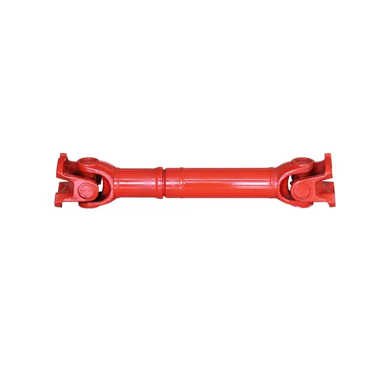
Are cardan joints suitable for both high-torque and high-speed applications?
Cardan joints can be used in a variety of applications, but their suitability for high-torque and high-speed applications depends on several factors. Here’s a detailed explanation of the considerations regarding the use of cardan joints in such scenarios:
1. High-Torque Applications: Cardan joints are generally well-suited for high-torque applications. The design of the joint allows for the transmission of significant torque between misaligned shafts. However, it is important to consider the specific torque requirements and operating conditions. Factors such as the size and type of the joint, the material used, and the application’s torque demands should be taken into account. In extremely high-torque applications, alternative coupling mechanisms such as gear couplings or universal joints may be more appropriate.
2. High-Speed Applications: While cardan joints can operate at relatively high speeds, there are some limitations to consider. At high rotational speeds, cardan joints can experience increased vibration, imbalance, and potential for fatigue failure. The rotating components of the joint can generate centrifugal forces, which can impact the balance and stability of the system. To mitigate these issues, careful design considerations, including balancing and vibration analysis, may be necessary. In some cases, alternative coupling mechanisms like flexible couplings or constant velocity joints may be better suited for high-speed applications.
3. Balancing and Vibration Control: Balancing the rotating components, such as the driveshaft and the joint itself, is essential for minimizing vibration issues in high-torque and high-speed applications. Imbalance can lead to increased vibrations, reduced efficiency, and potential damage to the joint and other system components. Proper balancing techniques, including dynamic balancing during manufacturing or precision balancing during installation, can help achieve smoother operation and minimize vibration problems.
4. Material Selection: The material used in the construction of the cardan joint plays a crucial role in its suitability for high-torque and high-speed applications. High-strength materials, such as alloy steels, are often preferred for their ability to handle increased torque loads. Additionally, materials with good fatigue resistance and high-speed capabilities can help ensure the durability and reliability of the joint in demanding applications.
5. Application-Specific Factors: The suitability of cardan joints for high-torque and high-speed applications also depends on the specific requirements and operating conditions of the application. Factors such as load characteristics, duty cycles, temperature, and environmental conditions should be considered. It is important to consult with the manufacturer or engineering experts to determine the appropriate size, type, and configuration of the cardan joint for a particular high-torque or high-speed application.
In summary, cardan joints can be suitable for both high-torque and high-speed applications, but careful consideration of factors such as torque requirements, speed limitations, balancing, material selection, and application-specific conditions is necessary. Evaluating these factors and consulting with experts can help determine the optimal coupling solution for a given high-torque or high-speed application.
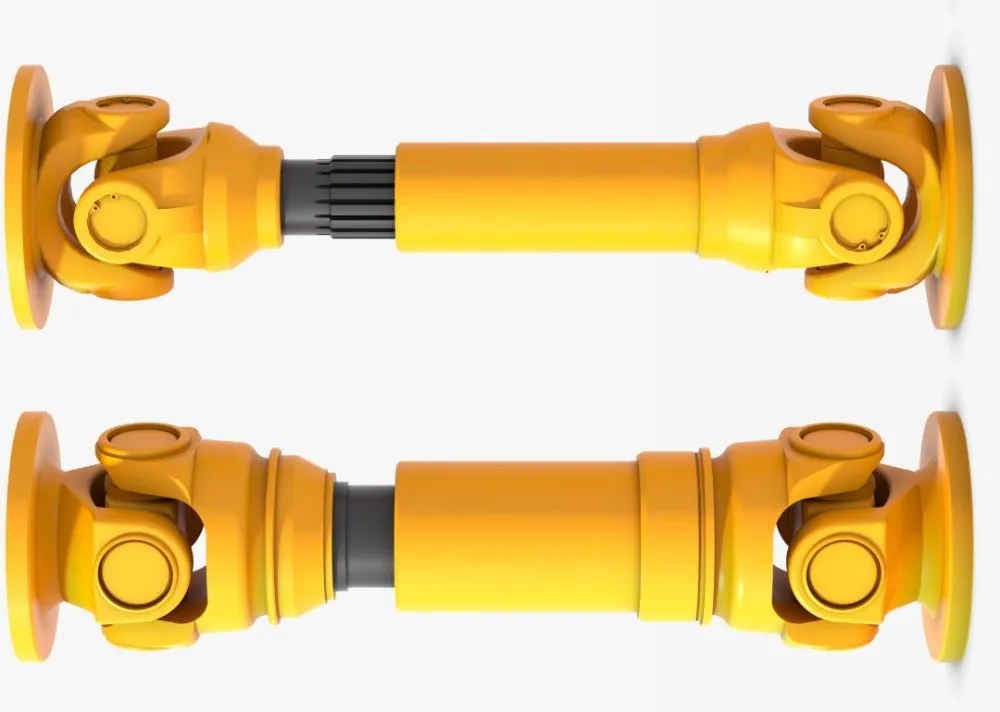
What are the safety considerations when working with cardan joints?
Working with cardan joints requires careful attention to safety to prevent accidents, injuries, and equipment damage. Cardan joints are mechanical components used for torque transmission and misalignment compensation, and they operate under various loads and conditions. Here are important safety considerations to keep in mind when working with cardan joints:
- Proper Training and Knowledge: Ensure that individuals working with cardan joints have proper training and understanding of their operation, installation, and maintenance. Adequate knowledge of safe working practices, procedures, and potential hazards associated with cardan joints is crucial.
- Personal Protective Equipment (PPE): Use appropriate personal protective equipment, such as safety glasses, gloves, and protective clothing, when handling cardan joints. PPE protects against potential hazards like flying debris, sharp edges, or accidental contact with rotating components.
- Lockout/Tagout: Before performing any maintenance or repair work involving cardan joints, follow lockout/tagout procedures to isolate and de-energize the system. This prevents accidental startup or movement of machinery, ensuring the safety of personnel working on or near the cardan joints.
- Secure Mounting and Fastening: Ensure that cardan joints are securely mounted and properly fastened to prevent unexpected movement or dislodgment during operation. Loose joints or fasteners can lead to component failure, sudden movements, or damage to other parts of the system.
- Torque and Load Limits: Adhere to the recommended torque and load limits specified by the manufacturer for the cardan joints. Exceeding these limits can result in premature wear, deformation, or failure of the joints, posing safety risks and compromising the overall system’s functionality.
- Regular Inspection and Maintenance: Implement a regular inspection and maintenance program for the cardan joints. Inspect for signs of wear, damage, or misalignment, and address any issues promptly. Lubricate the joints according to the manufacturer’s recommendations to ensure smooth operation and prevent excessive friction or overheating.
- Safe Handling and Lifting: When handling or lifting cardan joints, use appropriate lifting equipment and techniques. Cardan joints can be heavy, and improper lifting can lead to strain or injuries. Ensure that lifting devices have the capacity to handle the weight of the joints safely.
- Avoid Contact with Rotating Components: Never reach into or make contact with rotating components of a system that incorporates cardan joints while the system is in operation. Keep loose clothing, jewelry, and other items away from moving parts to prevent entanglement or injury.
- Proper Disposal of Used or Damaged Joints: Follow proper disposal procedures for used or damaged cardan joints. Consult local regulations and guidelines for the disposal of mechanical components to minimize environmental impact and ensure compliance with safety and waste management standards.
- Manufacturer’s Guidelines: Always refer to and follow the manufacturer’s guidelines, instructions, and warnings specific to the cardan joints being used. Manufacturers provide important safety information, installation procedures, and maintenance recommendations specific to their products.
By addressing these safety considerations, individuals can mitigate potential risks associated with working with cardan joints, promote a safe working environment, and ensure the reliable and efficient operation of the systems they are integrated into.
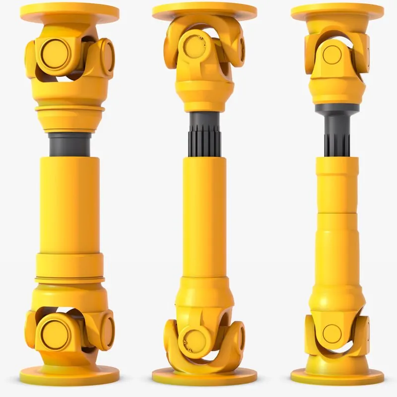
How do you install a cardan joint?
Installing a cardan joint involves several steps to ensure proper alignment, secure attachment, and reliable operation. Here’s a detailed explanation of the process for installing a cardan joint:
- Prepare the Components: Gather all the necessary components for the installation, including the cardan joint, yokes, bearings, retaining rings, and any additional hardware required. Ensure that the components are clean and free from dirt, debris, or damage.
- Align the Shafts: Position the input and output shafts that will be connected by the cardan joint. Align the shafts as closely as possible to minimize misalignment. The shafts should be collinear and positioned at the desired angle or position for the specific application.
- Attach the Yokes: Attach the yokes to the input and output shafts. The yokes typically have holes or bores that match the diameter of the shafts. Securely fasten the yokes to the shafts using appropriate fasteners, such as set screws or bolts. Ensure that the yokes are tightly secured to prevent any movement or slippage during operation.
- Assemble the Cardan Joint: Assemble the cardan joint by connecting the yokes with the cross-shaped component. The cross should fit snugly into the yoke holes or bores. Apply a suitable lubricant to the bearings to ensure smooth rotation and reduce friction. Some cardan joints may have retaining rings or clips to secure the bearings in place. Make sure all the components are properly aligned and seated.
- Check for Clearance: Verify that there is adequate clearance between the cardan joint and any surrounding components, such as chassis or housing. Ensure that the cardan joint can rotate freely without any obstructions or interference. If necessary, adjust the positioning or mounting of the cardan joint to provide sufficient clearance.
- Perform a Trial Run: Before finalizing the installation, perform a trial run to check the functionality of the cardan joint. Rotate the connected shafts manually or with a suitable power source and observe the movement of the joint. Ensure that there are no unusual noises, binding, or excessive play. If any issues are detected, investigate and address them before proceeding.
- Secure the Cardan Joint: Once the functionality is confirmed, secure the cardan joint in its final position. This may involve tightening additional fasteners or locking mechanisms to keep the joint in place. Use the appropriate torque specifications provided by the manufacturer to ensure proper tightening without damaging the components.
- Perform Final Checks: Double-check all the connections, fasteners, and clearances to ensure that everything is properly installed and secured. Verify that the cardan joint operates smoothly and without any issues. Inspect the entire system for any signs of misalignment, excessive vibration, or other abnormalities.
It is important to follow the specific installation instructions provided by the manufacturer of the cardan joint, as different designs and configurations may have specific requirements. If you are unsure or unfamiliar with the installation process, it is recommended to consult the manufacturer’s documentation or seek assistance from a qualified professional to ensure a proper and safe installation of the cardan joint.


editor by CX 2023-11-21