Error:获取session失败,
|
US $400-600 / Piece | |
1 Piece (Min. Order) |
###
| After-sales Service: | All Lifecycle |
|---|---|
| Warranty: | 1 Year |
| Material: | Carbon Steel |
| Surface Treatment: | Baking Paint |
| Customized: | Non-Customized |
| Standard: | Standard |
###
| Samples: |
US$ 600/Piece
1 Piece(Min.Order) |
|---|
###
| Customization: |
Available
|
|---|
###
| Model No. | Brake Specification | Length of Handbrake Wire |
| TED1015 | ϕ254×48.5 | Left:1090mm Right:1390mm |
###
| Model No. | Brake Specification | Length of Handbrake Wire |
| TED20 | ϕ310×60 | Left:1270mm Right:1790mm |
###
| Model No. | Brake Specification | Length of Handbrake Wire |
| TED20J | ϕ310×60 | Left:1270mm Right:1790mm |
###
| Model No. | Brake Specification | Length of Handbrake Wire |
| TED30 | ϕ314×76 | Left:1270mm Right:1790mm |
###
| Model No. | Axle Load | Axle Net Weight | Brake Specification |
| TED5060 | ϕ314×76 | 550kgs | ϕ317×90 |
| Brake Oil Inlet | Hand Brake | Gear Oil | Input Torque |
| M12×1 | EQ140 | 85W/90(GL-5) | 1100N.m |
###
| Model No. | TED70 | |
| Main Transmission Ratio | 6.33 | |
| Transmission Ratio At Wheel | 4.25 | |
| Total Transmission Ratio | 26.9 | |
| Axle Load | 15000Kg | |
| Input Torque | 2100N.m | |
| Clamp-disc Type Brake | Cylinder Quantity | 4 |
| Cylinder Diameter | 75mm | |
| Braking Oil Pressure | 9.8MPa | |
| Braking Radius | R150 | |
| Braking Moment | 4000N.m/pc | |
|
US $400-600 / Piece | |
1 Piece (Min. Order) |
###
| After-sales Service: | All Lifecycle |
|---|---|
| Warranty: | 1 Year |
| Material: | Carbon Steel |
| Surface Treatment: | Baking Paint |
| Customized: | Non-Customized |
| Standard: | Standard |
###
| Samples: |
US$ 600/Piece
1 Piece(Min.Order) |
|---|
###
| Customization: |
Available
|
|---|
###
| Model No. | Brake Specification | Length of Handbrake Wire |
| TED1015 | ϕ254×48.5 | Left:1090mm Right:1390mm |
###
| Model No. | Brake Specification | Length of Handbrake Wire |
| TED20 | ϕ310×60 | Left:1270mm Right:1790mm |
###
| Model No. | Brake Specification | Length of Handbrake Wire |
| TED20J | ϕ310×60 | Left:1270mm Right:1790mm |
###
| Model No. | Brake Specification | Length of Handbrake Wire |
| TED30 | ϕ314×76 | Left:1270mm Right:1790mm |
###
| Model No. | Axle Load | Axle Net Weight | Brake Specification |
| TED5060 | ϕ314×76 | 550kgs | ϕ317×90 |
| Brake Oil Inlet | Hand Brake | Gear Oil | Input Torque |
| M12×1 | EQ140 | 85W/90(GL-5) | 1100N.m |
###
| Model No. | TED70 | |
| Main Transmission Ratio | 6.33 | |
| Transmission Ratio At Wheel | 4.25 | |
| Total Transmission Ratio | 26.9 | |
| Axle Load | 15000Kg | |
| Input Torque | 2100N.m | |
| Clamp-disc Type Brake | Cylinder Quantity | 4 |
| Cylinder Diameter | 75mm | |
| Braking Oil Pressure | 9.8MPa | |
| Braking Radius | R150 | |
| Braking Moment | 4000N.m/pc | |
Types of Axles
An axle is the central shaft of a rotating wheel or gear. It can be fixed to the wheels or to the vehicle itself. Depending on the design, it may be fixed in different positions and have different types of mounting points. It may also have bearings. Axles come in different types and shapes. Some of them are more functional than others, and they may be semi-floating, tandem-drive, or lift axles.
Customized axles work best for cars
Adding big horsepower to a car can increase its performance, but this addition can also cause problems. It is important to take proper measurements for the rear axle to ensure it is not too long or too short. However, this measurement can become complicated with limited-slip differentials and offset pinions.
If you want to add custom axles to your car, it is important to know the physical properties of the axle and what kind of load it can handle. If you’re only planning to make a minor upgrade, it may be enough to get a standard axle. However, if you’re planning to make any major modifications, a customized axle will be a much better option.
Customized axles can be made of a variety of materials. They can be made of carbon steel or nickel steel. Some are made to float freely and others are made to be rigid. If you’re building a car, you should also consider the type of bearings and kingpins that it will use.
Axles come in a variety of types, based on the amount of force they produce. Some are pre-defined, while others are customized to meet your car’s specifications. The advantages of customizing your axles include improved wheel speed and torque. You can even adjust the angle of the axles for even more performance.
Axles can make or break your car’s performance. Customized axles are made with a proprietary alloy material that increases the torsional strength. Because of this, they are able to withstand a tremendous amount of power. Additionally, they are able to withstand lateral and bending loads.
While customizing your axle is an excellent idea, it is also very expensive. The best way to go about it is to work with a professional. They are able to make the axles you need and they’re usually well-made and made of quality materials. However, you should make sure you check the reviews and ratings of the manufacturer before making a purchase.
If you want to shorten the axle on your car, you should have it machined with new splines. The number of splines on an axle is important because it determines the strength of the axle. A 33-spline axle is more durable than a 28-spline axle, and a 40-spline axle is even stronger.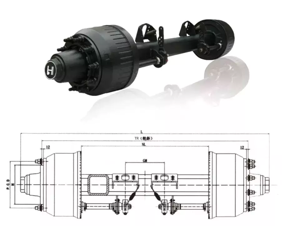
Semi-floating axles
Semi-floating rear axles are a common type of axle used in midsize trucks. They utilize a single wheel support bearing and use one axle shaft to transmit rotation to the wheels. A semi-floating axle is typically lubricated. Aftermarket kits are available to make the axle shaft stronger. However, these kits do not upgrade the axle differential assembly. Therefore, axles with weak differential assemblies may not benefit from conversion.
Semi-floating axles feature a “C-Clip” for holding the axle shaft in place in the axle casing. The problem with this design is that the axle shaft is exposed to more wear and tear. In addition, axle shafts with a C-Clip must be surface-hardened in the area where the axle shaft is flexed.
Semi-floating axles differ from full-floating axles in their appearance. A semi-floating axle has a hub that looks like the hub of a 3/4-ton 14-bolt Ford axle, whereas a full-floating axle’s hub looks like that of a 1 ton Ford axle.
Semi-floating axles have a tapered end. This makes them more efficient in carrying weight. In addition, they have a keyed end to prevent the rear hub from slipping around. This ensures the axle remains stable even when the rear wheels are turning. It is also important to note that semi-floating axles can only carry a small amount of weight, while full-floating axles can carry a lot of weight.
Semi-floating axles are lighter than full-float axles, which makes them less expensive to manufacture. Additionally, if one axle fails, the vehicle will continue to operate normally. Aside from this, semi-floating axles also have c-clips, which are the bearings that bear the weight of the vehicle.
A semi-floating axle is also available with an optional 5-lug hub. The axle shaft transmits rotational torque from the differential to the wheel, and the hub rides on tapered roller bearings. A full-floating axle assembly is stronger than a semi-floating axle system. In addition, it is compatible with factory 5-lug hubs.
Semi-floating axles are easier to install than full-floating axles. However, if you want to convert your semi-floating axle to a full-floating axle, you can install an aftermarket kit.
Tandem-drive axles
A tandem drive axle is a type of axle with two wheels on one side of the vehicle. Compared to a single axle with two wheels, a tandem drive axle is 60 pounds lighter and offers improved performance and durability. This type of axle is designed to optimize fleet uptime by balancing design efficiency and application-specific demands.
The suspension system of a tandem drive axle includes air springs that control the suspension of the lead and trailing axles. The air springs are pneumatically connected to a common reservoir. The springs’ displacements are averaged to provide a controlling input to the air spring pressurization controller.
A tandem drive axle may be used to transport heavier loads. It is important to note that the maximum weight of a tandem drive axle may be different in different states. In general, the federal regulations allow up to 34K pounds per axle, but the state regulations may be different. However, the weight limits of tandem axle groups are significantly lower than for single axles.
A tandem drive axle is a common type of vehicle drive axle. It is characterized by two axles spaced more than 40 inches apart. The distances are measured from the axle centers. A tandem-drive axle may be a drive axle or a steer axle. If the steer axle is overloaded, steering will be more difficult.
A tandem drive axle is a popular choice for commercial trucks. It is durable and can handle heavy loads. It is often used in cement mixing trucks and tanker trucks, where the weight of the load is distributed evenly between the two axles. The combination of the two axles helps a tandem drive truck make a smoother start from a stopped position. Because the weight is distributed across two axles, the torque generated by the engine can be distributed more effectively.
A tandem drive axle is usually paired with two air-lift axles. A tandem drive axle is also used when the weight of a cargo truck cannot be supported by the two air-lift axles. Tandem-drive axles are typically installed at the rear of a truck’s chassis.
Lift axles
Lift axles are a great way to reduce the workload on your powertrain, while also improving your fuel economy. These axles reduce rolling resistance, thrust, and tandem scrub, and can improve fuel economy by two to five percent. However, you should use lift axles with care, and pay special attention to suspension spacing.
Some lift axles have a steering feature, which allows the driver to control when the axle is raised, which is useful for taking sharp corners. However, some drawbacks to non-steerable lift axles include excessive tire wear. Steerable lift axles can alleviate this problem, but they are generally more expensive.
Another benefit of lift axles is that they increase a vehicle’s weight carrying capacity. This is useful for trucks with large load capacities. Although state laws vary, federal regulations are generally in favor of spreading the weight of a truck’s cargo across several axles. This helps protect large road pavements and bridges.
Lift axles are an important feature of dump trucks and should be considered if you’re considering making a change. However, they can be costly, and it’s important to consider the costs and benefits before deciding on a new configuration. These axles are best used when the load capacity of a truck is more than double what it is capable of carrying.
The developed algorithm has been tested under various scenarios. First, the algorithm accepts the command from the driver to lift axles. However, it ignores the tag axle dropping command if the vehicle is traveling more than 30 kph. Second, the vehicle stops for about 60 seconds. Once loaded, the algorithm drops the axles in order.
Besides enhancing the weight carrying capacity of a truck, lift axles are also used for auxiliary purposes. Most of these axles are used on dump trucks. In addition to the pusher axle, some dump trucks have a tag axle, which increases the distance between the steer axle and rearmost axle. This allows the truck to carry more cargo than the pusher axle.

editor by czh 2022-12-12


