Product Description
Factory Customized For CHINAMFG HOWO/Steyr Foton-Auman Truck Parts Automobile Cardan Cross Shaft Universal Joint 991.1431.0082
Helpful Links
For instant communication, please click here
For our catalogs, please click here
For our home page, please click here
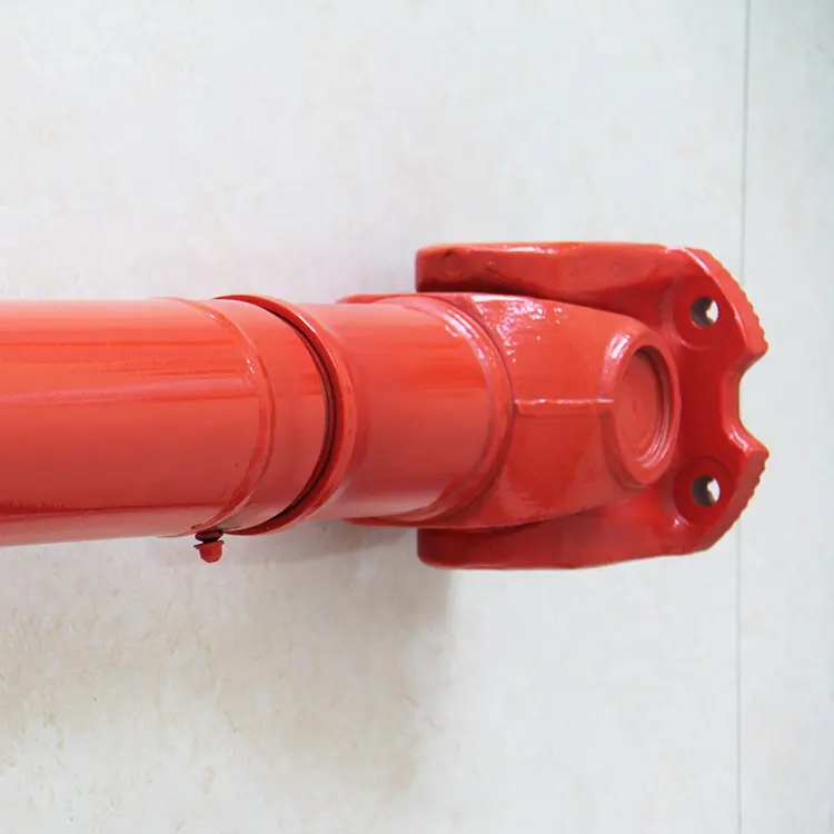
(1) The universal joint material 40Cr 40C is an alloy structural steel that has excellent comprehensive mechanical properties after quenching and tempering.
(2) The internal roller needle of the universal joint is made of high-quality bearing steel, which increases its wear resistance and greatly increases its service life.
(3) The parts have been filled with butter at the factory to increase their rotational flexibility.
(4) The product is shipped out individually and undergoes multiple inspection procedures to ensure smooth and stable loading.
More Products
| Truck Model | Sinotruk, Shacman, CHINAMFG Auman, CHINAMFG Xihu (West Lake) Dis., Xihu (West Lake) Dis.feng, Xihu (West Lake) Dis.feng Liuqi Balong, North BENZ( BEIBEN), C&C, JAC, etc. | |
| Product catalogue | Axle | Wheel Assembly |
| Differential Assembly | ||
| Main Reducer Assembly | ||
| Inner Ring Gear& Bracket | ||
| Basin Angle Gear/ Bevel Gear | ||
| Axle Shaft/ Half Shaft & Through Shaft | ||
| Axle Housing& Axle Assembly | ||
| Steering knuckle & Front Axle | ||
| Gear | ||
| Brake Drum& Wheel Hub | ||
| Flange | ||
| Bearing | ||
| Main Reducer Housing | ||
| Oil Seal Seat | ||
| Nut& Shim Series | ||
| Brake Backing Plate | ||
| Chassis Support Products | Leaf Spring Bracket | |
| Drop Arm Series | ||
| Bracket Series | ||
| Leaf Spring Shackle Series | ||
| Balanced Suspension Series | Balance Shaft Assembly | |
| Balance Shaft Housing | ||
| Axle Spring Seat | ||
| Thrust Rod | ||
| Balance Shaft Parts | ||
| Shock Absorber Series | Shock Absorber | |
| Shock Absorbing Airbag | ||
| Steering System | Power Steering Pump | |
| Power Steering Gear | ||
| Rubber Products | Oil Seal | |
| Rubber Support | ||
| Thrust Rod Rubber Core | ||
| Truck Belt | ||
| Engine support | ||
| Other | ||
| Clutch Series | Clutch Pressure Plate | |
| Clutch Disc | ||
| Flywheel Assembly | ||
| Flywheel Ring Gear | ||
| Adjusting Arm Series | ||
Factory Show
Our factory is located in HangZhou, ZheJiang , China. The production workshop covers an area of 3,200 square meters, the assembly workshop covers an area of 2,200 square meters, and the warehouse covers an area of 3,800 square meters. We have a mature production system and product research and development capabilities, rich assembly experience, and advanced testing equipment. Provide you with competitive and high quality products.
Packaging & Shipping
FAQ
Q1. Are you a factory or trading company?
We are a factory integrating research, development, production and sales.
Q2. What are the advantages of your products?
We support product customization to meet customer needs for special products. We can strictly control the products from raw materials to production, processing, product quality inspection, delivery, packaging, etc., and provide customers with high-end products and the most advantageous prices.
Q3. How about products price?
We are a factory, all products are direct sale at factory price. For the same price, we will provide the best quality; for the same quality, we have the most advantageous price.
Q4. What is your terms of packing?
We have branded packaging and neutral packaging, and we can also do what you want with authorization. This is flexible.
Q5. How to guarantee your after-sales service?
Strict inspection during production, Strictly check the products before shipment to ensure our packaging in good condition. Track and receive feedback from customer regularly. Our products warranty is 365 days.
Each product provides quality assurance service. If there is a problem with the product within the warranty period, the customer can negotiate with us in detail about the related claims, and we will do our best to satisfy the customer.
/* January 22, 2571 19:08:37 */!function(){function s(e,r){var a,o={};try{e&&e.split(“,”).forEach(function(e,t){e&&(a=e.match(/(.*?):(.*)$/))&&1
| After-sales Service: | Support |
|---|---|
| Warranty: | 12 Months |
| Condition: | New |
| Samples: |
US$ 5/Piece
1 Piece(Min.Order) | Order Sample |
|---|
| Customization: |
Available
| Customized Request |
|---|
.shipping-cost-tm .tm-status-off{background: none;padding:0;color: #1470cc}
| Shipping Cost:
Estimated freight per unit. |
about shipping cost and estimated delivery time. |
|---|
| Payment Method: |
|
|---|---|
|
Initial Payment Full Payment |
| Currency: | US$ |
|---|
| Return&refunds: | You can apply for a refund up to 30 days after receipt of the products. |
|---|

How does a cardan joint affect the overall efficiency of a system?
A cardan joint can have an impact on the overall efficiency of a system in several ways. While it offers the ability to transmit rotational motion between misaligned shafts, there are factors to consider that can affect the efficiency of the system. Here’s a detailed explanation of how a cardan joint can influence overall system efficiency:
- Power Transmission Efficiency: Cardan joints introduce mechanical connections and moving parts into the system, which can result in power losses due to friction, backlash, and misalignment. These losses can reduce the overall power transmission efficiency of the system. The efficiency can be further affected by the condition of the joint, such as wear, lubrication, and alignment. Regular maintenance, proper lubrication, and minimizing misalignment can help mitigate power losses and improve efficiency.
- Angular Limitations: Cardan joints have specific angular operating ranges within which they can effectively transmit power. Operating the joint beyond these limits can result in increased friction, binding, and reduced efficiency. It is important to ensure that the operating angles of the joint are within the manufacturer’s specified range to maintain optimal efficiency. In cases where large operating angles are required, alternative coupling mechanisms or constant velocity joints may be more efficient options.
- Vibration and Imbalance: Cardan joints introduce additional components and connections, which can contribute to increased vibration and imbalance in the system. Vibrations can result in energy losses and reduced efficiency. Imbalance can cause uneven loading on the connected components, leading to increased wear and decreased efficiency. Proper balancing of the joint and the connected components, as well as monitoring and addressing excessive vibrations, are important for maintaining system efficiency.
- Maintenance and Lubrication: The efficiency of a system utilizing a cardan joint can be influenced by the maintenance practices and lubrication of the joint. Insufficient or improper lubrication can increase friction and wear, leading to reduced efficiency. Regular maintenance, including lubrication, inspection for wear, and alignment checks, is essential for optimal joint performance and efficiency. Following the manufacturer’s recommendations and guidelines for maintenance can help ensure maximum efficiency.
- System Integration and Design: The overall efficiency of a system also depends on the integration and design considerations of the cardan joint. Proper alignment, minimizing misalignment, and optimizing the selection and sizing of the joint and connected components are crucial for achieving efficient power transmission. Careful system design, including the selection of appropriate shafts, bearings, and supporting structures, can contribute to minimizing energy losses and improving overall efficiency.
- Application-Specific Factors: The impact of a cardan joint on system efficiency can vary depending on the specific application and operating conditions. Factors such as load requirements, rotational speeds, operating environment, and duty cycles can influence the efficiency of the system. It is important to consider these application-specific factors and evaluate the suitability of a cardan joint in terms of its ability to meet the efficiency requirements of the system.
Considering these factors and implementing appropriate measures, such as regular maintenance, proper lubrication, alignment checks, and system optimization, can help mitigate the potential efficiency drawbacks of a cardan joint and ensure the optimal performance of the overall system.

What are the key design considerations for optimizing cardan joint performance?
Optimizing the performance of a cardan joint requires careful design considerations that take into account various factors influencing its functionality, durability, and efficiency. By addressing these key design considerations, the performance of the cardan joint can be enhanced. Here’s a detailed explanation:
1. Mechanical Load and Torque Requirements: Understand the mechanical load and torque requirements of the application in which the cardan joint will be used. This includes analyzing the magnitude, direction, and variability of the loads and torques that the joint will experience. Properly selecting the cardan joint’s size, material, and configuration based on these requirements is crucial for optimizing its performance.
2. Operating Speed and Angular Misalignment: Consider the operating speed and the expected angular misalignment between the input and output shafts. The design of the cardan joint should accommodate the required speed range and angular movements while maintaining smooth operation and torque transmission. Balancing the joint’s ability to handle misalignments with its rotational capabilities is essential for optimizing performance.
3. Material Selection: Choose appropriate materials for the cardan joint components based on factors such as strength, durability, and resistance to wear and corrosion. Consider the specific operating conditions, including temperature, humidity, and exposure to chemicals or contaminants. Selecting high-quality materials that can withstand the application’s demands is crucial for optimizing performance and longevity.
4. Critical Dimensions and Clearances: Pay attention to critical dimensions and clearances within the cardan joint design. These include the size and geometry of the joint’s components, as well as the clearances between them. Properly dimensioning these aspects ensures sufficient strength, flexibility, and clearance for smooth operation and efficient torque transmission.
5. Lubrication and Sealing: Implement effective lubrication and sealing mechanisms to minimize friction, wear, and the ingress of contaminants. Proper lubrication ensures smooth operation and reduces power losses due to friction. Sealing the joint against dust, moisture, and other environmental factors helps maintain its performance and extend its lifespan.
6. Bearing and Bushing Design: Consider the design and selection of bearings or bushings used within the cardan joint. These components play a crucial role in supporting the joint’s rotational movement and transferring torque. Proper bearing or bushing selection, based on load capacity, lubrication requirements, and expected lifespan, is essential for optimizing the joint’s performance and reducing wear.
7. Structural Integrity and Rigidity: Ensure that the cardan joint assembly is structurally sound and rigid. Adequate stiffness and strength prevent excessive deflection and deformation during operation, leading to improved torque transmission efficiency and reduced wear on the joint and connected components.
8. Manufacturability and Quality Control: Consider manufacturability aspects during the design phase to ensure that the cardan joint can be produced consistently and cost-effectively. Implement quality control measures to verify dimensional accuracy, material quality, and functional performance of the manufactured joints, ensuring that they meet the required specifications and performance criteria.
9. Environmental Factors: Take into account environmental factors such as temperature variations, humidity, presence of corrosive agents, or exposure to vibrations. Design the cardan joint to withstand these conditions and incorporate appropriate protective measures or materials to ensure long-term performance and reliability.
10. Maintenance and Serviceability: Consider ease of maintenance and serviceability when designing the cardan joint. Provide access to lubrication points, inspection areas, and potential wear points for efficient maintenance activities. Designing for easy disassembly and replacement of worn components can minimize downtime and extend the joint’s lifespan.
By carefully addressing these key design considerations, the performance of a cardan joint can be optimized, resulting in improved torque transmission, durability, and overall efficiency. It is important to evaluate the specific requirements of the application and consult with experienced engineers or designers specializing in drivetrain systems to ensure the best design practices are followed.

Can you explain the purpose of a cardan joint in a drive shaft?
A cardan joint, also known as a universal joint or U-joint, serves a crucial purpose in a drive shaft. The drive shaft is responsible for transmitting rotational motion and torque from the engine or power source to the wheels or driven components. Here’s a detailed explanation of the purpose of a cardan joint in a drive shaft:
A drive shaft is a mechanical component that connects the output of the engine or power source to the wheels or driven components of a vehicle or machinery. It is typically a tubular shaft that rotates at high speeds and transmits the torque generated by the engine to propel the vehicle or operate the machinery. The drive shaft needs to accommodate various factors, including changes in distance, misalignment, and different angles between the engine and the wheels or driven components.
This is where the cardan joint comes into play. The cardan joint is located at each end of the drive shaft, connecting it to the engine or power source and the wheels or driven components. The purpose of the cardan joint is to allow the drive shaft to transmit rotational motion and torque while accommodating the misalignment and changes in angles that occur between these components.
When the engine or power source rotates, it generates rotational motion and torque. The cardan joint at the engine end of the drive shaft receives this rotational motion and torque and transfers it to the drive shaft. As the drive shaft rotates, the cardan joint allows for the changes in angle and misalignment between the engine and the wheels or driven components. This flexibility of the cardan joint ensures that the drive shaft can operate smoothly and transmit power effectively, even when the components are not perfectly aligned or when there are variations in the angles.
At the other end of the drive shaft, another cardan joint is present to connect the drive shaft to the wheels or driven components. This cardan joint receives the rotational motion and torque from the drive shaft and transfers it to the wheels or driven components, allowing them to rotate and perform their intended functions.
The cardan joint in the drive shaft effectively compensates for misalignment, changes in angles, and variations in distance between the engine and the wheels or driven components. It ensures that the rotational motion and torque generated by the engine can be transmitted smoothly and efficiently to propel the vehicle or operate the machinery.
Overall, the purpose of the cardan joint in a drive shaft is to provide flexibility and accommodate misalignment, allowing for the effective transmission of rotational motion and torque between the engine or power source and the wheels or driven components.


editor by CX 2024-05-17
China factory Wuxi CZPT Brand Cardan Shaft Spare Parts Universal Joint
Product Description
HangZhou Xihu (West Lake) Dis. Brand Cardan Shaft Spare Parts Universal Joint
Brief Introduction
Processing flow
Quality Control
Packaging & Delivery
Packaging details:Standard plywood case
Delivery detail: 3-15 working days,depend on the actual produce condition
FAQ
Q1: What is the location of your company?
A1: Our company is located in the HangZhou City ,ZheJiang ,China.Welcome to visit our factory at anytime!
Q2: How does your factory do regarding quality control?
A2: Our standard QC system to control quality.
Q3: What is your delivery time?
A3: Usually within 20 days after the receipt of payment.Delivery time must depend on the actual produce condition.
Q4: What are your strengths?
A4: 1.We are the manufacturer,having competitive advantage in price.
2.A large part of money is put into advancing CNC equipments and product
R&D department annual,the performance of cardan shaft can be guaranteed.
3.About quality issues or follow-up after-sales service,we report directly to the boss.
Specification
There is no uniform standard for the specifications of cross assemblies. Please contact us directly for confirmation.
/* January 22, 2571 19:08:37 */!function(){function s(e,r){var a,o={};try{e&&e.split(“,”).forEach(function(e,t){e&&(a=e.match(/(.*?):(.*)$/))&&1
| Condition: | New |
|---|---|
| Color: | Silver |
| Certification: | ISO, BV |
| Structure: | Cross |
| Material: | Forging |
| Type: | Cross |
| Customization: |
Available
| Customized Request |
|---|

How do you calculate the torque capacity of a universal joint?
Calculating the torque capacity of a universal joint involves considering various factors such as the joint’s design, material properties, and operating conditions. Here’s a detailed explanation:
The torque capacity of a universal joint is determined by several key parameters:
- Maximum Allowable Angle: The maximum allowable angle, often referred to as the “operating angle,” is the maximum angle at which the universal joint can operate without compromising its performance and integrity. It is typically specified by the manufacturer and depends on the joint’s design and construction.
- Design Factor: The design factor accounts for safety margins and variations in load conditions. It is a dimensionless factor typically ranging from 1.5 to 2.0, and it is multiplied by the calculated torque to ensure the joint can handle occasional peak loads or unexpected variations.
- Material Properties: The material properties of the universal joint’s components, such as the yokes, cross, and bearings, play a crucial role in determining its torque capacity. Factors such as the yield strength, ultimate tensile strength, and fatigue strength of the materials are considered in the calculations.
- Equivalent Torque: The equivalent torque is the torque value that represents the combined effect of the applied torque and the misalignment angle. It is calculated by multiplying the applied torque by a factor that accounts for the misalignment angle and the joint’s design characteristics. This factor is often provided in manufacturer specifications or can be determined through empirical testing.
- Torque Calculation: To calculate the torque capacity of a universal joint, the following formula can be used:
Torque Capacity = (Equivalent Torque × Design Factor) / Safety Factor
The safety factor is an additional multiplier applied to ensure a conservative and reliable design. The value of the safety factor depends on the specific application and industry standards but is typically in the range of 1.5 to 2.0.
It is important to note that calculating the torque capacity of a universal joint involves complex engineering considerations, and it is recommended to consult manufacturer specifications, guidelines, or engineering experts with experience in universal joint design for accurate and reliable calculations.
In summary, the torque capacity of a universal joint is calculated by considering the maximum allowable angle, applying a design factor, accounting for material properties, determining the equivalent torque, and applying a safety factor. Proper torque capacity calculations ensure that the universal joint can reliably handle the expected loads and misalignments in its intended application.
How does a constant-velocity (CV) joint differ from a traditional universal joint?
A constant-velocity (CV) joint differs from a traditional universal joint in several ways. Here’s a detailed explanation:
A traditional universal joint (U-joint) and a constant-velocity (CV) joint are both used for transmitting torque between non-aligned or angularly displaced shafts. However, they have distinct design and operational differences:
- Mechanism: The mechanism of torque transmission differs between a U-joint and a CV joint. In a U-joint, torque is transmitted through a set of intersecting shafts connected by a cross or yoke arrangement. The angular misalignment between the shafts causes variations in speed and velocity, resulting in fluctuating torque output. On the other hand, a CV joint uses a set of interconnected elements, typically ball bearings or roller bearings, to maintain a constant velocity and torque output, regardless of the angular displacement between the input and output shafts.
- Smoothness and Efficiency: CV joints offer smoother torque transmission compared to U-joints. The constant velocity output of a CV joint eliminates speed fluctuations, reducing vibrations and allowing for more precise control and operation. This smoothness is particularly advantageous in applications where precise motion control and uniform power delivery are critical. Additionally, CV joints operate with higher efficiency as they minimize energy losses associated with speed variations and friction.
- Angular Capability: While U-joints are capable of accommodating larger angular misalignments, CV joints have a limited angular capability. U-joints can handle significant angular displacements, making them suitable for applications with extreme misalignment. In contrast, CV joints are designed for smaller angular displacements and are typically used in applications where constant velocity is required, such as automotive drive shafts.
- Operating Angles: CV joints can operate at larger operating angles without significant loss in torque or speed. This makes them well-suited for applications that require larger operating angles, such as front-wheel drive vehicles. U-joints, on the other hand, may experience speed fluctuations and reduced torque transmission capabilities at higher operating angles.
- Complexity and Size: CV joints are generally more complex in design compared to U-joints. They consist of multiple components, including inner and outer races, balls or rollers, cages, and seals. This complexity often results in larger physical dimensions compared to U-joints. U-joints, with their simpler design, tend to be more compact and easier to install in tight spaces.
In summary, a constant-velocity (CV) joint differs from a traditional universal joint (U-joint) in terms of torque transmission mechanism, smoothness, efficiency, angular capability, operating angles, complexity, and size. CV joints provide constant velocity output, smoother operation, and higher efficiency, making them suitable for applications where precise motion control and uniform power delivery are essential. U-joints, with their ability to accommodate larger angular misalignments, are often preferred for applications with extreme misalignment requirements.

Can you provide examples of vehicles that use universal joints?
Universal joints are commonly used in various types of vehicles for transmitting torque between shafts that are not in a straight line or are at an angle to each other. Here are some examples of vehicles that use universal joints:
- Automobiles: Universal joints are widely used in automobiles for transmitting torque from the engine to the rear wheels in rear-wheel drive vehicles. They are commonly found in the driveline, connecting the transmission or gearbox to the driveshaft, and in the driveshaft itself. Universal joints are also used in front-wheel drive vehicles for transmitting torque from the transaxle to the front wheels.
- Trucks and commercial vehicles: Universal joints are utilized in trucks and commercial vehicles for transmitting torque between various components of the drivetrain. They can be found in the driveshaft, connecting the transmission or gearbox to the rear differential or axle assembly.
- Off-road vehicles and SUVs: Universal joints are extensively used in off-road vehicles and SUVs that have four-wheel drive or all-wheel drive systems. They are employed in the driveline to transmit torque from the transmission or transfer case to the front and rear differentials or axle assemblies.
- Military vehicles: Universal joints are utilized in military vehicles for transmitting torque between different components of the drivetrain, similar to their use in trucks and off-road vehicles. They provide reliable torque transfer in demanding off-road and rugged environments.
- Agricultural and construction machinery: Universal joints are commonly found in agricultural and construction machinery, such as tractors, combines, excavators, loaders, and other heavy equipment. They are used in the drivelines and power take-off (PTO) shafts to transmit torque from the engine or motor to various components, attachments, or implements.
- Marine vessels: Universal joints are employed in marine vessels for transmitting torque between the engine and the propeller shaft. They are used in various types of watercraft, including boats, yachts, ships, and other marine vessels.
- Aircraft: Universal joints are utilized in certain aircraft applications, such as helicopters, to transmit torque between the engine and the rotor assembly. They allow for angular displacement and smooth transmission of power in the complex rotor systems of helicopters.
- Industrial machinery: Universal joints find applications in various types of industrial machinery, including manufacturing equipment, conveyors, pumps, and other power transmission systems. They enable torque transmission between non-aligned or angularly displaced shafts in industrial settings.
Please note that the specific usage of universal joints may vary depending on the vehicle design, drivetrain configuration, and application requirements. Different types of universal joints, such as single joint, double joint, constant velocity (CV) joint, or Cardan joint, may be employed based on the specific needs of the vehicle or machinery.
editor by CX 2024-05-06
China Best Sales Wuxi CZPT Brand Cardan Shaft Spare Parts Universal Joint
Product Description
HangZhou Xihu (West Lake) Dis. Brand Cardan Shaft Spare Parts Universal Joint
Brief Introduction
Processing flow
Quality Control
Packaging & Delivery
Packaging details:Standard plywood case
Delivery detail: 3-15 working days,depend on the actual produce condition
FAQ
Q1: What is the location of your company?
A1: Our company is located in the HangZhou City ,ZheJiang ,China.Welcome to visit our factory at anytime!
Q2: How does your factory do regarding quality control?
A2: Our standard QC system to control quality.
Q3: What is your delivery time?
A3: Usually within 20 days after the receipt of payment.Delivery time must depend on the actual produce condition.
Q4: What are your strengths?
A4: 1.We are the manufacturer,having competitive advantage in price.
2.A large part of money is put into advancing CNC equipments and product
R&D department annual,the performance of cardan shaft can be guaranteed.
3.About quality issues or follow-up after-sales service,we report directly to the boss.
Specification
There is no uniform standard for the specifications of cross assemblies. Please contact us directly for confirmation.
/* January 22, 2571 19:08:37 */!function(){function s(e,r){var a,o={};try{e&&e.split(“,”).forEach(function(e,t){e&&(a=e.match(/(.*?):(.*)$/))&&1
| Condition: | New |
|---|---|
| Color: | Silver |
| Certification: | ISO, BV |
| Structure: | Cross |
| Material: | Forging |
| Type: | Cross |
| Customization: |
Available
| Customized Request |
|---|

What is the role of needle bearings in a universal joint?
Needle bearings play a critical role in the operation of a universal joint. Here’s a detailed explanation:
A universal joint, also known as a U-joint, is a mechanical coupling that allows the transmission of rotational motion between two misaligned shafts. It consists of a cross-shaped component with needle bearings positioned at each end of the cross.
The role of needle bearings in a universal joint is to facilitate smooth rotation and efficient power transmission while accommodating the misalignment between the shafts. Here are the key functions of needle bearings:
- Reducing Friction: Needle bearings are designed to minimize friction and provide a low-resistance interface between the rotating components of the universal joint. The needle-like rollers in the bearings have a large surface area in contact with the inner and outer raceways, distributing the load evenly. This design reduces frictional losses and ensures efficient power transmission.
- Accommodating Misalignment: Universal joints are often used to transmit motion between shafts that are not perfectly aligned. Needle bearings are capable of accommodating angular misalignment, allowing the shafts to operate at different angles while maintaining smooth rotation. The flexibility of the needle bearings enables the universal joint to compensate for misalignment and transmit torque without excessive stress or wear.
- Supporting Radial Loads: In addition to transmitting torque, needle bearings in a universal joint also provide support for radial loads. Radial loads are forces acting perpendicular to the shaft’s axis, and the needle bearings are designed to handle these loads while maintaining proper alignment and rotation. This capability is particularly important in applications where the universal joint experiences varying loads or vibrations.
- Enhancing Durability: Needle bearings are designed to withstand high-speed rotation, heavy loads, and demanding operating conditions. They are typically made of hardened steel or other durable materials that offer high strength and wear resistance. The robust construction of the needle bearings ensures long-lasting performance and reliability in the universal joint.
- Providing Lubrication: Proper lubrication is crucial for the smooth operation and longevity of needle bearings. Lubricants, such as grease or oil, are applied to the needle bearings to reduce friction, dissipate heat, and prevent premature wear. The lubrication also helps to protect the bearings from contamination and corrosion, especially in marine or harsh environments.
Overall, needle bearings in a universal joint enable efficient power transmission, accommodate misalignment, support radial loads, enhance durability, and require proper lubrication. They are essential components that contribute to the smooth and reliable operation of the universal joint in various applications, including automotive drivelines, industrial machinery, and aerospace systems.
What is the effect of varying operating angles on the performance of a universal joint?
Varying operating angles can have a significant effect on the performance of a universal joint. Here’s a detailed explanation:
A universal joint is designed to transmit rotational motion between two shafts that are not collinear or have a constant angular relationship. The operating angle refers to the angle between the input and output shafts of the joint. The effects of varying operating angles on the performance of a universal joint are as follows:
- Changes in Torque and Speed: As the operating angle of a universal joint increases or decreases, the torque and speed transmitted through the joint can be affected. At small operating angles, the torque and speed transmission are relatively efficient. However, as the operating angle increases, the torque and speed capacity of the joint may decrease. This reduction in torque and speed capability is due to increased non-uniform loading and bending moments on the joint’s components.
- Increased Vibrations and Noise: Varying operating angles can introduce vibrations and noise in a universal joint. As the operating angle becomes more extreme, the joint experiences higher levels of dynamic imbalance and misalignment. This imbalance can lead to increased vibration levels, which may affect the overall performance and lifespan of the joint. Additionally, the non-uniform motion and increased stress on the joint’s components can generate additional noise during operation.
- Angular Misalignment Compensation: One of the primary advantages of universal joints is their ability to compensate for angular misalignment between shafts. By accommodating varying operating angles, the joint allows for flexibility in transmitting motion even when the input and output shafts are not perfectly aligned. However, extreme operating angles may challenge the joint’s ability to compensate for misalignment effectively. Very large operating angles can lead to increased wear, decreased joint life, and potential loss of motion transmission efficiency.
- Increased Wear and Fatigue: Varying operating angles can contribute to increased wear and fatigue on the universal joint’s components. As the operating angle increases, the joint experiences higher levels of stress and non-uniform loading. This stress concentration can lead to accelerated wear and fatigue, especially at critical areas such as the bearing caps and needle bearings. Continuous operation at extreme operating angles without proper lubrication and maintenance can significantly reduce the joint’s lifespan.
- Heat Generation: Extreme operating angles can result in increased heat generation within the universal joint. The non-uniform motion and increased friction caused by high operating angles can lead to elevated temperatures. Excessive heat can accelerate lubricant breakdown, increase wear rates, and potentially cause premature failure of the joint. Adequate cooling and proper lubrication are essential to mitigate the effects of heat generation in such cases.
- Efficiency and Power Loss: Varying operating angles can impact the overall efficiency of a universal joint. At small to moderate operating angles, the joint can transmit motion with relatively high efficiency. However, as the operating angle increases, the joint’s efficiency may decrease due to increased friction, bending moments, and non-uniform loading. This reduction in efficiency can result in power loss and decreased overall system performance.
Therefore, it is crucial to consider the effects of varying operating angles on the performance of a universal joint. Proper design, careful selection of operating angles within the joint’s specified limits, regular maintenance, and adherence to manufacturer guidelines can help mitigate the potential negative effects and ensure optimal performance and longevity of the joint.

Are there different types of universal joints available?
Yes, there are different types of universal joints available to suit various applications and requirements. Let’s explore some of the commonly used types:
- Single Joint (Cardan Joint): The single joint, also known as a Cardan joint, is the most basic and widely used type of universal joint. It consists of two yokes connected by a cross-shaped center piece. The yokes are typically 90 degrees out of phase with each other, allowing for angular displacement and misalignment between shafts. Single joints are commonly used in automotive drivelines and industrial applications.
- Double Joint: A double joint, also referred to as a double Cardan joint or a constant velocity joint, is an advanced version of the single joint. It consists of two single joints connected in series with an intermediate shaft in between. The use of two joints in series helps to cancel out the velocity fluctuations and reduce vibration caused by the single joint. Double joints are commonly used in automotive applications, especially in front-wheel-drive vehicles, to provide constant velocity power transmission.
- Tracta Joint: The Tracta joint, also known as a tripod joint or a three-roller joint, is a specialized type of universal joint. It consists of three rollers or balls mounted on a spider-shaped center piece. The rollers are housed in a three-lobed cup, allowing for flexibility and articulation. Tracta joints are commonly used in automotive applications, particularly in front-wheel-drive systems, to accommodate high-speed rotation and transmit torque smoothly.
- Rzeppa Joint: The Rzeppa joint is another type of constant velocity joint commonly used in automotive applications. It features six balls positioned in grooves on a central sphere. The balls are held in place by an outer housing with an inner race. Rzeppa joints provide smooth power transmission and reduced vibration, making them suitable for applications where constant velocity is required, such as drive axles in vehicles.
- Thompson Coupling: The Thompson coupling, also known as a tripodal joint, is a specialized type of universal joint. It consists of three interconnected rods with spherical ends. The arrangement allows for flexibility and misalignment compensation. Thompson couplings are often used in applications where high torque transmission is required, such as industrial machinery and power transmission systems.
These are just a few examples of the different types of universal joints available. Each type has its own advantages and is suitable for specific applications based on factors such as torque requirements, speed, angular displacement, and vibration reduction. The selection of the appropriate type of universal joint depends on the specific needs of the application.
editor by CX 2024-04-11
China Professional Truck Auto Parts Cardan Shaft Universal Cross Joint Bearing
Product Description
Truck Auto Parts Cardan Shaft Universal Cross Joint
| ZheJiang CHINAMFG Heavy Truck Components Co., Ltd
|
|||
Who we are?
The most professional truck and spare parts manufacturer in China;
The leading truck and spare parts exporter in China;
The most comprehensive truck and spare parts solution provider in China;
The most worry-free and most satisfactory and reputable supplier for you in China.
We can never let you down if you choose us.
FAQ
1)What about your packing?
Generally,our spare parts are packed in anti-rust paper,plastic bag,box,carton or according to customer’s requirements.
2)What about your terms of payment?
L/C, T/T, D/P, Western Union, Paypal Money Gram, Others
3)What is your terms of delivery?
EXW,FOB,CFR,CIF
4)How about your delivery time?
Usually,it will take around 3~7 days after your advance payment,it depends on the items and quantities of your order.
5)What is your sample policy?
We can supply the samples if the samples are in stock,but the customers will pay the sample cost and the delivery cost(or freight collect)
Our Services:
1.All of our products are with professional service.
2.We can offer all kinds of OEM spare parts according to the customer’s requirements.
3. We can offer free consultation of service information .
4.The dominance we kept all along is to provide the customers with genuine spare parts.
5.Standard export packag to protect the parts from long-distance delivery.
6. Professional sales and after sale service team, timely and efficiently to solve your problem.
7.We are willing to privide the High Quality,ReasonablePrice and Perfect Service. /* January 22, 2571 19:08:37 */!function(){function s(e,r){var a,o={};try{e&&e.split(“,”).forEach(function(e,t){e&&(a=e.match(/(.*?):(.*)$/))&&1
| Truck Model: | 70mineking |
|---|---|
| Delivery Time: | 3~7 Days |
| MOQ: | 1PCS |
| Payment: | T/T, West Union |
| Transport Package: | Box/Wooden Pallet/Carton |
| Specification: | Standard |
| Samples: |
US$ 14/Piece
1 Piece(Min.Order) | |
|---|
| Customization: |
Available
| Customized Request |
|---|

Can cardan joints be used in heavy-duty machinery and equipment?
Yes, cardan joints can be used in heavy-duty machinery and equipment. Cardan joints, also known as universal joints, are versatile mechanical couplings that transmit torque between misaligned shafts. They offer several advantages that make them suitable for heavy-duty applications. Here’s a detailed explanation of why cardan joints can be used in heavy-duty machinery and equipment:
- Torque Transmission: Cardan joints are capable of transmitting high levels of torque between misaligned shafts. This makes them well-suited for heavy-duty applications that require the transfer of substantial power. The design of the joint allows for smooth torque transmission, even in cases where the shafts are not perfectly aligned.
- Misalignment Compensation: In heavy-duty machinery and equipment, misalignments between shafts can occur due to factors such as thermal expansion, vibration, or structural flexing. Cardan joints excel at compensating for such misalignments. Their flexible design accommodates angular, parallel, and axial misalignments, allowing for reliable operation in challenging industrial environments.
- Durability and Strength: Heavy-duty machinery and equipment often operate under demanding conditions, subjecting components to high loads and harsh environments. Cardan joints are typically constructed from durable materials such as alloy steels, which provide excellent strength and resistance to fatigue and wear. This durability enables them to withstand the heavy loads and prolonged operation associated with heavy-duty applications.
- Compact Design: Cardan joints have a compact design, which is advantageous in heavy-duty machinery and equipment where space constraints may be present. Their compactness allows for efficient installation and integration within the system, making them suitable for applications where minimizing size and weight is important.
- Versatility: Cardan joints are available in various sizes and configurations to accommodate different heavy-duty applications. They can be customized to meet specific torque and speed requirements, making them versatile for use in a wide range of machinery and equipment, including industrial machinery, construction equipment, agricultural machinery, and more.
While cardan joints are generally suitable for heavy-duty applications, it is important to consider certain factors to ensure optimal performance. These factors include proper selection of the joint size and type based on the application requirements, adherence to specified torque and speed limits, regular maintenance to prevent wear and ensure proper lubrication, and consideration of any environmental factors that may affect the joint’s performance.
In summary, cardan joints can indeed be used in heavy-duty machinery and equipment due to their excellent torque transmission capabilities, ability to compensate for misalignments, durability, compact design, and versatility. By considering the specific requirements of the application and following appropriate maintenance practices, cardan joints can provide reliable and efficient operation in heavy-duty industrial settings.
What are the safety considerations when working with cardan joints?
Working with cardan joints requires careful attention to safety to prevent accidents, injuries, and equipment damage. Cardan joints are mechanical components used for torque transmission and misalignment compensation, and they operate under various loads and conditions. Here are important safety considerations to keep in mind when working with cardan joints:
- Proper Training and Knowledge: Ensure that individuals working with cardan joints have proper training and understanding of their operation, installation, and maintenance. Adequate knowledge of safe working practices, procedures, and potential hazards associated with cardan joints is crucial.
- Personal Protective Equipment (PPE): Use appropriate personal protective equipment, such as safety glasses, gloves, and protective clothing, when handling cardan joints. PPE protects against potential hazards like flying debris, sharp edges, or accidental contact with rotating components.
- Lockout/Tagout: Before performing any maintenance or repair work involving cardan joints, follow lockout/tagout procedures to isolate and de-energize the system. This prevents accidental startup or movement of machinery, ensuring the safety of personnel working on or near the cardan joints.
- Secure Mounting and Fastening: Ensure that cardan joints are securely mounted and properly fastened to prevent unexpected movement or dislodgment during operation. Loose joints or fasteners can lead to component failure, sudden movements, or damage to other parts of the system.
- Torque and Load Limits: Adhere to the recommended torque and load limits specified by the manufacturer for the cardan joints. Exceeding these limits can result in premature wear, deformation, or failure of the joints, posing safety risks and compromising the overall system’s functionality.
- Regular Inspection and Maintenance: Implement a regular inspection and maintenance program for the cardan joints. Inspect for signs of wear, damage, or misalignment, and address any issues promptly. Lubricate the joints according to the manufacturer’s recommendations to ensure smooth operation and prevent excessive friction or overheating.
- Safe Handling and Lifting: When handling or lifting cardan joints, use appropriate lifting equipment and techniques. Cardan joints can be heavy, and improper lifting can lead to strain or injuries. Ensure that lifting devices have the capacity to handle the weight of the joints safely.
- Avoid Contact with Rotating Components: Never reach into or make contact with rotating components of a system that incorporates cardan joints while the system is in operation. Keep loose clothing, jewelry, and other items away from moving parts to prevent entanglement or injury.
- Proper Disposal of Used or Damaged Joints: Follow proper disposal procedures for used or damaged cardan joints. Consult local regulations and guidelines for the disposal of mechanical components to minimize environmental impact and ensure compliance with safety and waste management standards.
- Manufacturer’s Guidelines: Always refer to and follow the manufacturer’s guidelines, instructions, and warnings specific to the cardan joints being used. Manufacturers provide important safety information, installation procedures, and maintenance recommendations specific to their products.
By addressing these safety considerations, individuals can mitigate potential risks associated with working with cardan joints, promote a safe working environment, and ensure the reliable and efficient operation of the systems they are integrated into.

How do you choose the right size cardan joint for your application?
Choosing the right size cardan joint for your application is crucial to ensure optimal performance, reliability, and longevity. Several factors need to be considered when selecting the appropriate size of a cardan joint. Here’s a detailed explanation of the key considerations:
- Load Capacity: Determine the maximum load that the cardan joint will need to transmit. Consider both the torque (rotational force) and the axial load (thrust) that will be applied to the joint. The load capacity of the cardan joint should exceed the maximum expected loads in your application to ensure safe and reliable operation.
- Operating Speed: Consider the rotational speed at which the cardan joint will be operating. Higher speeds may require specific design considerations, such as balancing, lubrication, and material selection, to ensure smooth operation and avoid premature wear or failure. Verify that the selected cardan joint is rated for the intended operating speed range.
- Shaft Diameter: Measure the diameter of the input and output shafts that will be connected by the cardan joint. The cardan joint should have yokes and bearings that match the shaft diameter to ensure a proper fit and reliable power transmission. It is essential to consider both shaft diameters when selecting a cardan joint.
- Misalignment Angle: Determine the maximum expected misalignment angle between the input and output shafts. Different types of cardan joints have different capabilities to accommodate misalignment. Consider the angular misalignment and choose a cardan joint that can handle the required range of misalignment angles in your application.
- Environmental Factors: Evaluate the operating environment of the cardan joint. Consider factors such as temperature, humidity, dust, chemicals, and vibration. Choose a cardan joint that is suitable for the specific environmental conditions to ensure proper functioning and longevity.
- Service Life and Maintenance: Consider the expected service life of the cardan joint and the maintenance requirements. Some applications may require frequent maintenance or periodic lubrication of the joint. Evaluate the ease of maintenance and factor it into your selection process.
- Standards and Regulations: Depending on your industry or application, there may be specific standards or regulations that dictate the requirements for cardan joints. Ensure that the selected cardan joint complies with the relevant standards and regulations for your application.
It is advisable to consult with a knowledgeable supplier or engineer specializing in power transmission components to assist you in selecting the right size cardan joint for your specific application. They can consider all the relevant factors and provide guidance to ensure optimal performance and reliability of the cardan joint in your application.
editor by CX 2024-03-14
China Standard Wuxi CZPT Brand Cardan Shaft Spare Parts Universal Joint
Product Description
HangZhou Xihu (West Lake) Dis. Brand Cardan Shaft Spare Parts Universal Joint
Brief Introduction
Processing flow
Quality Control
Packaging & Delivery
Packaging details:Standard plywood case
Delivery detail: 3-15 working days,depend on the actual produce condition
FAQ
Q1: What is the location of your company?
A1: Our company is located in the HangZhou City ,ZheJiang ,China.Welcome to visit our factory at anytime!
Q2: How does your factory do regarding quality control?
A2: Our standard QC system to control quality.
Q3: What is your delivery time?
A3: Usually within 20 days after the receipt of payment.Delivery time must depend on the actual produce condition.
Q4: What are your strengths?
A4: 1.We are the manufacturer,having competitive advantage in price.
2.A large part of money is put into advancing CNC equipments and product
R&D department annual,the performance of cardan shaft can be guaranteed.
3.About quality issues or follow-up after-sales service,we report directly to the boss.
Specification
There is no uniform standard for the specifications of cross assemblies. Please contact us directly for confirmation.
/* January 22, 2571 19:08:37 */!function(){function s(e,r){var a,o={};try{e&&e.split(“,”).forEach(function(e,t){e&&(a=e.match(/(.*?):(.*)$/))&&1
| Condition: | New |
|---|---|
| Color: | Silver |
| Certification: | ISO, BV |
| Structure: | Cross |
| Material: | Forging |
| Type: | Cross |
| Customization: |
Available
| Customized Request |
|---|

What are the potential limitations or drawbacks of using cardan joints?
While cardan joints offer numerous advantages in transmitting rotational motion between misaligned shafts, they also have certain limitations and drawbacks to consider. Here are some potential limitations associated with the use of cardan joints:
- Angular Limitations: Cardan joints have limited angularity or operating angles. They are designed to operate within specific angular ranges, and exceeding these angles can cause accelerated wear, increased vibration, and potential joint failure. Extreme operating angles can lead to binding, decreased efficiency, and reduced power transmission capacity. In applications where large operating angles are required, alternative flexible coupling mechanisms or constant velocity joints may be more suitable.
- Backlash and Torsional Stiffness: Cardan joints inherently exhibit some degree of backlash, which is the clearance or free play between the mating components. This can result in a slight delay in power transmission and can affect the precision of motion in certain applications. Additionally, cardan joints may have higher torsional stiffness compared to other coupling mechanisms, which can transmit higher vibrations and shocks to the connected components.
- Maintenance Requirements: Cardan joints require regular maintenance to ensure proper lubrication, alignment, and performance. The lubricant needs to be regularly replenished or replaced, and the joint should be inspected for wear, misalignment, or other issues. Failure to perform adequate maintenance can result in premature wear, reduced efficiency, and potential joint failure. Maintenance procedures may require specialized tools and expertise.
- Space and Weight: Cardan joints can occupy a significant amount of space due to their design and the need for perpendicular shafts. In applications with limited space constraints, finding suitable locations for cardan joints can be challenging. Additionally, the weight of cardan joints, especially in heavy-duty applications, can add to the overall weight of the system, which may have implications for fuel efficiency, payload capacity, or overall performance.
- Cost: Cardan joints, particularly high-quality and precision-engineered ones, can be relatively expensive compared to other coupling mechanisms. The complex design, manufacturing tolerances, and specialized materials involved contribute to their higher cost. In cost-sensitive applications, alternative coupling solutions may be considered if the angular limitations and other drawbacks of cardan joints are not critical.
- High-Speed Limitations: At high rotational speeds, cardan joints can experience increased vibration, imbalance, and potential for fatigue failure. The rotating components of the joint can generate centrifugal forces that impact the balance and stability of the system. In high-speed applications, careful design considerations, including balancing and vibration analysis, may be necessary to mitigate these issues.
It is important to evaluate the specific application requirements, operating conditions, and limitations when considering the use of cardan joints. While they offer versatility and flexibility in many scenarios, alternative coupling mechanisms may be more suitable in cases where the limitations and drawbacks of cardan joints pose significant challenges.
Can cardan joints be used in conveyor systems?
Yes, cardan joints can be used in conveyor systems, and they offer several advantages in certain applications. Cardan joints, also known as universal joints, are versatile mechanical couplings that provide flexibility in transmitting torque and accommodating misalignments between rotating shafts. Here’s a detailed explanation of the use of cardan joints in conveyor systems:
Conveyor systems are widely used in various industries for the efficient movement of bulk materials, goods, or components. These systems consist of multiple components, including conveyor belts, pulleys, rollers, and drive systems, that work together to transport materials from one location to another.
Cardan joints can be integrated into conveyor systems to enable torque transmission and accommodate misalignments in certain parts of the system. Here are some key considerations and advantages of using cardan joints in conveyor systems:
- Misalignment Compensation: Conveyor systems often require flexibility to accommodate misalignments between different components, such as pulleys and drive shafts. Cardan joints provide a flexible coupling solution that can handle angular, parallel, and axial misalignments, allowing smooth operation and minimizing stress on the system.
- Torque Transmission: Cardan joints are designed to transmit torque between shafts that are not aligned. In conveyor systems, they can be used to connect the drive shaft to the pulleys or rollers, allowing torque to be efficiently transferred throughout the system. This enables the movement of the conveyor belt and facilitates the transportation of materials along the desired path.
- Compact Design: Cardan joints offer a compact and space-saving design, making them suitable for conveyor systems with limited space constraints. Their small size allows for efficient integration into the system without compromising its overall footprint.
- High Load Capacity: Conveyor systems often handle significant loads, and the components must be capable of withstanding these loads. Cardan joints are designed to handle high torque and can transmit substantial loads, making them suitable for conveyor systems that require robust and reliable torque transmission.
- Variable Speed and Direction: Cardan joints provide the ability to transmit torque at various angles, allowing conveyor systems to operate at different speeds and change direction if needed. This flexibility allows for versatility in conveyor system design and adaptability to different material handling requirements.
- Reduced Vibrations and Noise: Cardan joints can help dampen vibrations and reduce noise levels in conveyor systems. The flexible coupling nature of the joint absorbs and dampens vibrations caused by the operation of the system, resulting in smoother and quieter performance.
- Application-Specific Considerations: The use of cardan joints in conveyor systems requires careful consideration of specific application requirements, such as the type of material being transported, system layout, operating conditions, and load characteristics. Proper selection of the cardan joint size, materials, lubrication, and maintenance practices is essential to ensure optimal performance and reliability.
It is worth noting that while cardan joints can offer advantages in certain conveyor system applications, other types of couplings or drive systems may be more suitable depending on the specific requirements and constraints of the system. Consulting with engineers and industry experts can help determine the most appropriate coupling solution for a given conveyor system.

How do you install a cardan joint?
Installing a cardan joint involves several steps to ensure proper alignment, secure attachment, and reliable operation. Here’s a detailed explanation of the process for installing a cardan joint:
- Prepare the Components: Gather all the necessary components for the installation, including the cardan joint, yokes, bearings, retaining rings, and any additional hardware required. Ensure that the components are clean and free from dirt, debris, or damage.
- Align the Shafts: Position the input and output shafts that will be connected by the cardan joint. Align the shafts as closely as possible to minimize misalignment. The shafts should be collinear and positioned at the desired angle or position for the specific application.
- Attach the Yokes: Attach the yokes to the input and output shafts. The yokes typically have holes or bores that match the diameter of the shafts. Securely fasten the yokes to the shafts using appropriate fasteners, such as set screws or bolts. Ensure that the yokes are tightly secured to prevent any movement or slippage during operation.
- Assemble the Cardan Joint: Assemble the cardan joint by connecting the yokes with the cross-shaped component. The cross should fit snugly into the yoke holes or bores. Apply a suitable lubricant to the bearings to ensure smooth rotation and reduce friction. Some cardan joints may have retaining rings or clips to secure the bearings in place. Make sure all the components are properly aligned and seated.
- Check for Clearance: Verify that there is adequate clearance between the cardan joint and any surrounding components, such as chassis or housing. Ensure that the cardan joint can rotate freely without any obstructions or interference. If necessary, adjust the positioning or mounting of the cardan joint to provide sufficient clearance.
- Perform a Trial Run: Before finalizing the installation, perform a trial run to check the functionality of the cardan joint. Rotate the connected shafts manually or with a suitable power source and observe the movement of the joint. Ensure that there are no unusual noises, binding, or excessive play. If any issues are detected, investigate and address them before proceeding.
- Secure the Cardan Joint: Once the functionality is confirmed, secure the cardan joint in its final position. This may involve tightening additional fasteners or locking mechanisms to keep the joint in place. Use the appropriate torque specifications provided by the manufacturer to ensure proper tightening without damaging the components.
- Perform Final Checks: Double-check all the connections, fasteners, and clearances to ensure that everything is properly installed and secured. Verify that the cardan joint operates smoothly and without any issues. Inspect the entire system for any signs of misalignment, excessive vibration, or other abnormalities.
It is important to follow the specific installation instructions provided by the manufacturer of the cardan joint, as different designs and configurations may have specific requirements. If you are unsure or unfamiliar with the installation process, it is recommended to consult the manufacturer’s documentation or seek assistance from a qualified professional to ensure a proper and safe installation of the cardan joint.
editor by CX 2024-03-11
China best Wuxi CZPT Brand Cardan Shaft Spare Parts Universal Joint
Product Description
HangZhou Xihu (West Lake) Dis. Brand Cardan Shaft Spare Parts Universal Joint
Brief Introduction
Processing flow
Quality Control
Packaging & Delivery
Packaging details:Standard plywood case
Delivery detail: 3-15 working days,depend on the actual produce condition
FAQ
Q1: What is the location of your company?
A1: Our company is located in the HangZhou City ,ZheJiang ,China.Welcome to visit our factory at anytime!
Q2: How does your factory do regarding quality control?
A2: Our standard QC system to control quality.
Q3: What is your delivery time?
A3: Usually within 20 days after the receipt of payment.Delivery time must depend on the actual produce condition.
Q4: What are your strengths?
A4: 1.We are the manufacturer,having competitive advantage in price.
2.A large part of money is put into advancing CNC equipments and product
R&D department annual,the performance of cardan shaft can be guaranteed.
3.About quality issues or follow-up after-sales service,we report directly to the boss.
Specification
There is no uniform standard for the specifications of cross assemblies. Please contact us directly for confirmation.
/* January 22, 2571 19:08:37 */!function(){function s(e,r){var a,o={};try{e&&e.split(“,”).forEach(function(e,t){e&&(a=e.match(/(.*?):(.*)$/))&&1
| Condition: | New |
|---|---|
| Color: | Silver |
| Certification: | ISO, BV |
| Structure: | Cross |
| Material: | Forging |
| Type: | Cross |
| Customization: |
Available
| Customized Request |
|---|
What is the role of needle bearings in a universal joint?
Needle bearings play a critical role in the operation of a universal joint. Here’s a detailed explanation:
A universal joint, also known as a U-joint, is a mechanical coupling that allows the transmission of rotational motion between two misaligned shafts. It consists of a cross-shaped component with needle bearings positioned at each end of the cross.
The role of needle bearings in a universal joint is to facilitate smooth rotation and efficient power transmission while accommodating the misalignment between the shafts. Here are the key functions of needle bearings:
- Reducing Friction: Needle bearings are designed to minimize friction and provide a low-resistance interface between the rotating components of the universal joint. The needle-like rollers in the bearings have a large surface area in contact with the inner and outer raceways, distributing the load evenly. This design reduces frictional losses and ensures efficient power transmission.
- Accommodating Misalignment: Universal joints are often used to transmit motion between shafts that are not perfectly aligned. Needle bearings are capable of accommodating angular misalignment, allowing the shafts to operate at different angles while maintaining smooth rotation. The flexibility of the needle bearings enables the universal joint to compensate for misalignment and transmit torque without excessive stress or wear.
- Supporting Radial Loads: In addition to transmitting torque, needle bearings in a universal joint also provide support for radial loads. Radial loads are forces acting perpendicular to the shaft’s axis, and the needle bearings are designed to handle these loads while maintaining proper alignment and rotation. This capability is particularly important in applications where the universal joint experiences varying loads or vibrations.
- Enhancing Durability: Needle bearings are designed to withstand high-speed rotation, heavy loads, and demanding operating conditions. They are typically made of hardened steel or other durable materials that offer high strength and wear resistance. The robust construction of the needle bearings ensures long-lasting performance and reliability in the universal joint.
- Providing Lubrication: Proper lubrication is crucial for the smooth operation and longevity of needle bearings. Lubricants, such as grease or oil, are applied to the needle bearings to reduce friction, dissipate heat, and prevent premature wear. The lubrication also helps to protect the bearings from contamination and corrosion, especially in marine or harsh environments.
Overall, needle bearings in a universal joint enable efficient power transmission, accommodate misalignment, support radial loads, enhance durability, and require proper lubrication. They are essential components that contribute to the smooth and reliable operation of the universal joint in various applications, including automotive drivelines, industrial machinery, and aerospace systems.

How do you address noise issues in a universal joint?
Noise issues in a universal joint can be addressed through various measures. Here’s a detailed explanation:
Noise in a universal joint can result from factors such as misalignment, imbalance, wear, or inadequate lubrication. Addressing noise issues involves identifying the underlying causes and implementing appropriate solutions. Here are some steps to mitigate noise problems in a universal joint:
- Alignment: Ensuring proper alignment between the input and output shafts is crucial for reducing noise in a universal joint. Misalignment can lead to increased stress, vibration, and noise generation. Aligning the shafts within the manufacturer’s specified tolerances helps minimize the angular deflection and associated noise.
- Balancing: Imbalance in the rotating components of a universal joint can contribute to noise generation. Balancing the yokes, crosses, or other relevant components helps minimize vibrations and noise. Techniques such as adding counterweights or using precision balancing equipment can help achieve better balance and reduce noise levels.
- Lubrication: Inadequate or improper lubrication can result in increased friction, wear, and noise in a universal joint. Using the manufacturer-recommended lubricant and following the specified lubrication intervals help ensure smooth operation and minimize noise. Regular maintenance, including lubrication checks and replenishment, is essential to mitigate noise issues arising from insufficient lubrication.
- Wear and Replacement: Wear in the universal joint components, such as the cross, bearings, or yokes, can contribute to noise. Regular inspection for signs of wear, such as pitting, scoring, or play, is necessary. If wear is detected, replacing the worn components with new ones that meet the manufacturer’s specifications can restore proper functionality and reduce noise.
- Vibration Damping: Implementing vibration damping techniques can help reduce noise in a universal joint. This may involve using vibration-absorbing materials, such as rubber or elastomeric elements, at appropriate locations to absorb and dissipate vibrations. Dampening vibrations helps minimize the transmission of noise and improves the overall performance of the joint.
- Proper Maintenance: Regular maintenance practices are vital for addressing noise issues in a universal joint. This includes periodic inspections, lubrication checks, and addressing any signs of misalignment, wear, or damage. Timely maintenance helps identify and rectify potential sources of noise before they escalate and affect the joint’s performance and reliability.
By implementing these measures and considering the specific operating conditions and requirements of the system, noise issues in a universal joint can be effectively addressed. It’s important to consult the manufacturer’s guidelines and recommendations for proper installation, operation, and maintenance to ensure optimal performance and minimize noise generation in the joint.
What are the benefits of using a universal joint in a mechanical system?
Using a universal joint in a mechanical system offers several benefits that contribute to the efficient and reliable operation of the system. Here are some of the key advantages:
- Misalignment compensation: One of the primary benefits of a universal joint is its ability to compensate for misalignment between rotating shafts. Universal joints can effectively transmit rotary motion between shafts that are not perfectly aligned, allowing for flexibility in system design and assembly. This flexibility accommodates various installation constraints and helps to minimize stress and wear on components.
- Angular motion transmission: Universal joints enable the transmission of angular motion between shafts that are not parallel or collinear. They can transfer rotational movement even when the shafts are at different angles to each other. This capability is particularly useful in applications where the shafts need to be connected at non-linear or offset angles, providing versatility and enabling complex mechanical systems.
- Torque transmission: Universal joints are capable of transmitting torque between shafts efficiently. They allow for the transfer of power from one shaft to another without a direct and rigid connection. This feature is especially important in applications where there may be slight misalignment or movement between the shafts due to factors like suspension systems, articulation, or vibration.
- Reduced vibration and shock absorption: Universal joints can help dampen vibration andshocks in a mechanical system. They absorb and distribute the impact forces caused by uneven movement or external disturbances, reducing the transmission of vibrations to other parts of the system. This feature is particularly beneficial in applications where smooth operation and reduced wear and tear are essential, such as automotive drivelines or industrial machinery.
- Constant velocity transmission: Certain types of universal joints, such as double joints or constant velocity joints, provide constant velocity transmission. These joints eliminate speed variations and maintain a consistent rotational speed even when the input and output shafts are at different angles. Constant velocity transmission is crucial in applications where precise and uniform motion is required, such as automotive steering systems or robotics.
- Flexibility and articulation: Universal joints offer flexibility and articulation, allowing for movement and rotation in multiple directions. They can accommodate changes in the orientation and position of connected shafts, providing mechanical systems with the ability to adapt to dynamic conditions. This flexibility is particularly advantageous in applications involving moving parts, such as suspension systems, robotic arms, or machinery with articulating components.
- Compact design: Universal joints are relatively compact in size, making them suitable for applications with space constraints. Their compact design allows for efficient integration into mechanical systems without occupying excessive space. This feature is valuable in various industries, including automotive, aerospace, and robotics, where optimizing space utilization is crucial.
- Reliability and durability: Universal joints are designed to be durable and reliable, with the ability to withstand high loads, torque, and operating conditions. They are constructed from robust materials and undergo rigorous testing to ensure long-lasting performance. This reliability makes them suitable for demanding applications in industries such as automotive, manufacturing, agriculture, and more.
The benefits of using a universal joint in a mechanical system contribute to improved functionality, increased efficiency, and extended component lifespan. By enabling misalignment compensation, angular motion transmission, torque transfer, vibration reduction, constant velocity transmission, flexibility, and compact design, universal joints enhance the overall performance and reliability of mechanical systems.
editor by CX 2024-03-09
China Standard Wuxi CZPT Brand Cardan Shaft Spare Parts Universal Joint
Product Description
HangZhou Xihu (West Lake) Dis. Brand Cardan Shaft Spare Parts Universal Joint
Brief Introduction
Processing flow
Quality Control
Packaging & Delivery
Packaging details:Standard plywood case
Delivery detail: 3-15 working days,depend on the actual produce condition
FAQ
Q1: What is the location of your company?
A1: Our company is located in the HangZhou City ,ZheJiang ,China.Welcome to visit our factory at anytime!
Q2: How does your factory do regarding quality control?
A2: Our standard QC system to control quality.
Q3: What is your delivery time?
A3: Usually within 20 days after the receipt of payment.Delivery time must depend on the actual produce condition.
Q4: What are your strengths?
A4: 1.We are the manufacturer,having competitive advantage in price.
2.A large part of money is put into advancing CNC equipments and product
R&D department annual,the performance of cardan shaft can be guaranteed.
3.About quality issues or follow-up after-sales service,we report directly to the boss.
Specification
There is no uniform standard for the specifications of cross assemblies. Please contact us directly for confirmation.
/* January 22, 2571 19:08:37 */!function(){function s(e,r){var a,o={};try{e&&e.split(“,”).forEach(function(e,t){e&&(a=e.match(/(.*?):(.*)$/))&&1
| Condition: | New |
|---|---|
| Color: | Silver |
| Certification: | ISO, BV |
| Structure: | Cross |
| Material: | Forging |
| Type: | Cross |
| Customization: |
Available
| Customized Request |
|---|
What is the role of needle bearings in a cardan joint?
Needle bearings play a crucial role in the smooth operation and performance of a cardan joint. They are commonly used as a type of rolling element bearing within the joint’s design. The primary role of needle bearings in a cardan joint is to provide support, reduce friction, and facilitate the transmission of torque between the joint’s components. Here’s a detailed explanation of the role of needle bearings in a cardan joint:
- Load Distribution: Needle bearings are designed to distribute loads evenly across their cylindrical rolling elements. In a cardan joint, they help distribute the axial and radial loads between the input and output shafts, yokes, and cross members. This load distribution capability helps minimize stress concentrations and ensures efficient torque transmission.
- Reduced Friction: The rolling motion of the needle bearings reduces the friction between the joint’s components. By reducing friction, needle bearings help minimize power losses and energy consumption within the cardan joint. This is particularly important in applications where efficiency and power transmission are critical.
- Misalignment Compensation: Cardan joints are designed to accommodate misalignments between the input and output shafts. Needle bearings allow a certain degree of misalignment while maintaining smooth rotation and torque transmission. Their design and arrangement provide flexibility and allow for angular, parallel, and axial misalignment compensation.
- High Load Capacity: Needle bearings are specially designed to handle high radial and axial loads. In a cardan joint, they are subjected to varying loads and torque forces. The robust construction of needle bearings enables them to withstand these loads while maintaining their structural integrity and performance.
- Compact Design: Needle bearings offer a high load capacity relative to their size, allowing for a more compact cardan joint design. Their small size and high load-carrying capability make them well-suited for applications with limited space or weight constraints.
- Reduced Wear and Longevity: Needle bearings are designed to have high wear resistance and durability. Their rolling motion reduces the sliding contact between the joint’s components, minimizing wear and extending the joint’s service life. This is particularly important in high-speed or high-load applications where wear can lead to premature failure.
- Operating Conditions: Needle bearings are designed to operate in a variety of conditions, including high-speed and high-temperature environments. They are often manufactured with high-quality materials and heat treatments to enhance their performance and reliability, making them suitable for demanding operating conditions commonly encountered in cardan joint applications.
Overall, needle bearings play a critical role in the functionality, efficiency, and longevity of a cardan joint. By providing load distribution, reduced friction, misalignment compensation, and high load capacity, they contribute to the smooth operation and reliable torque transmission of the joint. Proper selection, lubrication, and maintenance of needle bearings are essential to ensure optimal performance and maximize the lifespan of the cardan joint.

How do you ensure reliable and consistent performance in a cardan joint?
Ensuring reliable and consistent performance in a cardan joint requires attention to various factors, including proper design, maintenance, and operating practices. By following best practices and considering key considerations, the reliability and performance of a cardan joint can be optimized. Here’s a detailed explanation:
1. Proper Design and Selection: The first step is to ensure the cardan joint is properly designed and selected for the intended application. Consider factors such as load requirements, operating conditions (including speed and temperature), misalignment angles, and torque transmission needs. Choose a cardan joint that is appropriately sized and rated to handle the specific demands of the application.
2. Material Selection: Selecting the appropriate materials for the cardan joint is crucial for long-term performance. Consider factors such as strength, fatigue resistance, and corrosion resistance. The materials should be compatible with the operating environment and any potential exposure to chemicals, moisture, or extreme temperatures.
3. Regular Inspection and Maintenance: Implement a regular inspection and maintenance schedule to identify any signs of wear, damage, or misalignment. This includes checking for excessive play, backlash, or abnormal vibrations. Regularly lubricate the joint as per the manufacturer’s recommendations and ensure that seals are intact to prevent contamination.
4. Alignment and Installation: Proper alignment during installation is critical for optimal performance. Ensure that the joint is aligned correctly with the connected shafts to minimize misalignment and reduce stress on the joint. Precise alignment helps to minimize wear, maximize torque transmission efficiency, and extend the life of the joint.
5. Load Considerations: Be mindful of the loads applied to the cardan joint. Avoid exceeding the recommended load limits and consider factors such as shock loads, torsional forces, and variations in load during operation. Excessive loads can lead to premature wear, fatigue, and failure of the joint.
6. Temperature Management: Maintain suitable operating temperatures for the cardan joint. Excessive heat or extreme temperature fluctuations can affect the performance and longevity of the joint. Ensure proper cooling or lubrication mechanisms are in place if operating conditions generate significant heat.
7. Training and Operator Awareness: Provide proper training to operators and maintenance personnel regarding the cardan joint’s operation, maintenance requirements, and potential failure modes. Encourage regular inspection and reporting of any abnormalities to address issues promptly.
8. Consider Additional Measures: Depending on the application and specific requirements, additional measures can be implemented to enhance performance and reliability. This may include incorporating backlash compensation systems, using precision-aligned cardan joints, or integrating monitoring systems to detect early signs of wear or misalignment.
By considering these factors and implementing best practices, reliable and consistent performance can be achieved in a cardan joint. Regular monitoring, maintenance, and prompt corrective actions are essential to ensure the joint operates optimally and delivers the expected performance throughout its service life.
What is a cardan joint and how does it work?
A cardan joint, also known as a universal joint or U-joint, is a mechanical coupling used to transmit rotational motion between two shafts that are not collinear or have a constant angular relationship. It provides flexibility and accommodates misalignment between the shafts. Here’s a detailed explanation of how a cardan joint works:
A cardan joint consists of three main components: two yokes and a cross-shaped member called the cross or spider. The yokes are attached to the ends of the shafts that need to be connected, while the cross sits in the center, connecting the yokes.
The cross has four arms that intersect at a central point, forming a cross shape. Each arm has a bearing surface or trunnion on which the yoke of the corresponding shaft is mounted. The yokes are typically fork-shaped and have holes or bearings to accommodate the trunnions of the cross.
When the input shaft rotates, it transfers the rotational motion to one of the yokes. The cross, being connected to both yokes, transmits this motion to the other yoke and subsequently to the output shaft.
The key feature of a cardan joint is its ability to accommodate misalignment between the input and output shafts. This misalignment can be angular, axial, or both. As the input and output shafts are not collinear, the angles between the shafts cause the yokes to rotate at different speeds during operation.
The universal joint’s design allows the cross to rotate freely within the yokes, while still transferring motion from one shaft to the other. When the input shaft rotates, the yoke connected to it rotates with the shaft. This rotation causes the cross to tilt, as the other yoke is fixed to the output shaft. As a result, the angle between the arms of the cross changes, allowing for the compensation of misalignment.
As the cross tilts, the relative speeds of the yokes change, but the rotational motion is still transferred to the output shaft. The cardan joint effectively converts the input shaft’s rotation into a modified rotation at the output shaft, accommodating the misalignment between the two shafts.
It’s important to note that while cardan joints provide flexibility and can handle misalignment, they introduce certain limitations. These include non-uniform motion, increased vibration, backlash, and potential loss of efficiency at extreme operating angles. Regular maintenance, proper lubrication, and adherence to manufacturer guidelines are essential to ensure the optimal performance and longevity of cardan joints.
editor by CX 2024-02-28
China Best Sales Wuxi CZPT Brand Cardan Shaft Spare Parts Universal Joint
Product Description
HangZhou Xihu (West Lake) Dis. Brand Cardan Shaft Spare Parts Universal Joint
Brief Introduction
Processing flow
Quality Control
Packaging & Delivery
Packaging details:Standard plywood case
Delivery detail: 3-15 working days,depend on the actual produce condition
FAQ
Q1: What is the location of your company?
A1: Our company is located in the HangZhou City ,ZheJiang ,China.Welcome to visit our factory at anytime!
Q2: How does your factory do regarding quality control?
A2: Our standard QC system to control quality.
Q3: What is your delivery time?
A3: Usually within 20 days after the receipt of payment.Delivery time must depend on the actual produce condition.
Q4: What are your strengths?
A4: 1.We are the manufacturer,having competitive advantage in price.
2.A large part of money is put into advancing CNC equipments and product
R&D department annual,the performance of cardan shaft can be guaranteed.
3.About quality issues or follow-up after-sales service,we report directly to the boss.
Specification
There is no uniform standard for the specifications of cross assemblies. Please contact us directly for confirmation.
/* March 10, 2571 17:59:20 */!function(){function s(e,r){var a,o={};try{e&&e.split(“,”).forEach(function(e,t){e&&(a=e.match(/(.*?):(.*)$/))&&1
| Condition: | New |
|---|---|
| Color: | Silver |
| Certification: | ISO, BV |
| Structure: | Cross |
| Material: | Forging |
| Type: | Cross |
| Customization: |
Available
| Customized Request |
|---|
How do you calculate the torque capacity of a cardan joint?
Calculating the torque capacity of a cardan joint involves considering various factors such as the joint’s design, material properties, and operating conditions. The torque capacity determines the maximum amount of torque that the joint can transmit without failure. Here’s a detailed explanation of how to calculate the torque capacity of a cardan joint:
- Gather Design Information: Start by gathering the necessary design information about the cardan joint, including its dimensions, material properties, and geometry. This information typically includes the outer diameter, inner diameter, length, and material strength properties.
- Calculate Cross-Sectional Area: Use the outer and inner diameters of the joint to calculate its cross-sectional area. The cross-sectional area is required to determine the stress distribution and calculate the torque capacity. The formula to calculate the cross-sectional area of a solid shaft is:
- Consider Material Properties: The material properties of the cardan joint, such as its yield strength or ultimate tensile strength, are essential for calculating the torque capacity. These properties determine the maximum stress that the joint can withstand before failure.
- Calculate Maximum Shear Stress: Using the torque applied and the cross-sectional area, the maximum shear stress on the joint can be calculated. The torque applied to the joint is the driving force that needs to be transmitted. The formula to calculate the maximum shear stress is:
- Compare Shear Stress to Material Strength: Compare the calculated maximum shear stress to the material’s yield strength or ultimate tensile strength. Ensure that the shear stress is below the allowable stress to prevent the joint from exceeding its capacity. The allowable stress is typically a fraction of the material’s yield strength or ultimate tensile strength, depending on the safety factor used.
Area = π * (Outer Diameter^2 - Inner Diameter^2) / 4
Shear Stress = Torque / (Area * 0.5 * Joint Length)
It is important to note that the above calculation provides an approximate estimation of the torque capacity. The actual torque capacity of a cardan joint can be influenced by additional factors, such as the joint’s geometry, loading conditions, operating temperature, and dynamic effects. Consulting the manufacturer’s specifications, engineering standards, or conducting extensive testing is recommended for precise torque capacity determination.
Additionally, it is crucial to consider other factors such as misalignment compensation, fatigue resistance, and service life requirements when selecting a cardan joint for a specific application. These factors may influence the overall performance and reliability of the joint beyond its torque capacity.
How do you retrofit an existing mechanical system with a cardan joint?
When retrofitting an existing mechanical system with a cardan joint, careful planning and consideration of various factors are necessary to ensure a successful integration. The retrofitting process involves modifying the system to accommodate the cardan joint’s requirements for torque transmission and misalignment compensation. Here’s a detailed explanation of how to retrofit an existing mechanical system with a cardan joint:
- Evaluate the Existing System: Begin by thoroughly evaluating the existing mechanical system to understand its design, components, and operational requirements. Identify the areas where a cardan joint can be integrated effectively and assess the feasibility of retrofitting.
- Identify the Integration Points: Determine the specific locations within the system where the cardan joint will be installed. This could include areas where torque transmission or misalignment compensation is required, such as connections between shafts, pulleys, or other rotating components.
- Measurements and Compatibility: Take accurate measurements of the existing components and spaces where the cardan joint will be installed. Ensure that the dimensions and specifications of the cardan joint are compatible with the available space and the system’s requirements. Consider factors such as shaft sizes, torque ratings, misalignment angles, and operating conditions.
- Design Modifications: Based on the evaluation and measurements, make necessary design modifications to accommodate the cardan joint. This may involve modifying shaft ends, adding or removing components, or adjusting mounting positions. Ensure that the modifications do not compromise the structural integrity or functionality of the system.
- Installation and Alignment: Install the cardan joint at the identified integration points according to the manufacturer’s guidelines and engineering best practices. Pay attention to proper alignment, ensuring that the joint aligns with the shafts and other connected components. Precise alignment is crucial for efficient torque transmission and to prevent excessive wear or failure.
- Secure Mounting: Properly secure the cardan joint to the system, ensuring that it is firmly and securely mounted. Use appropriate fasteners, couplings, or brackets to hold the joint in place and prevent any movement or vibration that could affect its performance.
- Lubrication and Maintenance: Follow the manufacturer’s recommendations for lubrication and maintenance of the cardan joint. Proper lubrication helps reduce friction, wear, and heat generation, ensuring smooth operation and longevity of the joint. Establish a maintenance schedule to regularly inspect and maintain the retrofit components to prevent any potential issues.
- Testing and Validation: After the retrofitting is complete, perform thorough testing to validate the functionality and performance of the retrofitted system. Test for torque transmission, misalignment compensation, and overall system operation. Monitor the system during operation to ensure that the cardan joint performs as expected and does not introduce any adverse effects.
It is essential to consult with experienced engineers or professionals specializing in retrofitting and cardan joint applications during the process. They can provide valuable guidance, expertise, and assistance in selecting the appropriate cardan joint, making design modifications, and ensuring a successful retrofit of the existing mechanical system.
What are the applications of a cardan joint?
A cardan joint, also known as a universal joint or U-joint, has a wide range of applications across various industries. Its ability to transmit rotational motion and accommodate misalignment between shafts makes it suitable for different systems and machines. Here’s a detailed explanation of the applications of a cardan joint:
- Automotive Drivetrains: One of the primary applications of cardan joints is in automotive drivetrains. They are used in vehicles with rear-wheel drive, all-wheel drive, and four-wheel drive systems. Cardan joints help transmit power from the engine to the driveshaft, allowing the rotational motion to be transferred to the rear axle or all four wheels. They provide flexibility and compensation for misalignment between the engine, transmission, and rear differential.
- Industrial Machinery: Cardan joints find extensive use in various industrial machinery applications. They are commonly employed in power transmission systems, especially when there is a need to transmit rotational motion between non-collinear shafts. Cardan joints are used in conveyor systems, printing presses, machine tools, pumps, mixers, and many other industrial machines that require efficient transmission of rotational power.
- Aerospace and Aviation: Cardan joints have applications in the aerospace and aviation industries. They are used in aircraft control systems, such as the control linkages between the control surfaces (elevator, rudder, ailerons) and the cockpit controls. Cardan joints allow for the transmission of pilot input to the control surfaces while accommodating any misalignment or changes in angles during flight.
- Marine Propulsion: In marine applications, cardan joints are utilized in propulsion systems. They are commonly used in boat drivetrains to transfer rotational motion from the engine to the propeller shaft. Cardan joints enable the engine to be mounted at an angle or in a different position from the propeller shaft, compensating for the misalignment that can arise due to the boat’s hull shape and design.
- Railway Systems: Cardan joints play a role in railway systems, particularly in drivetrains and couplings. They are used in locomotives and train cars to transfer rotational motion between different components, such as the engine, gearbox, and wheel axle. Cardan joints provide flexibility and accommodate misalignment that may occur due to the movement and articulation of train cars on curved tracks.
- Mining and Construction Equipment: Cardan joints are employed in heavy-duty mining and construction equipment. They are used in applications such as excavators, loaders, bulldozers, and off-highway trucks. Cardan joints help transmit power and motion between different components of these machines, allowing them to operate efficiently and withstand the demanding conditions of mining and construction environments.
- Industrial Robotics: Cardan joints find applications in industrial robotics and automation. They are used in robotic arms and manipulators to transmit rotational motion between different segments or joints of the robotic system. Cardan joints enable precise and flexible movement, allowing robots to perform complex tasks in manufacturing, assembly, and other industrial processes.
These are just a few examples of the diverse applications of cardan joints. Their ability to handle misalignment, transmit rotational motion at varying angles, and provide flexibility make them a fundamental component in numerous systems and machines across industries.
editor by CX 2024-02-19
China Professional Auto Parts Steering Intermediate Shaft Extension Shaft Universal Joint for Saic CZPT Pickup T60 OEM C00059290
Product Description
Product Description
Product name: Auto Parts Steering Intermediate Shaft Extension Shaft Universal Joint For SAIC CHINAMFG Pickup T60 OEM C0057190
OEM Number: C0057190
Application: For SAIC CHINAMFG Pickup T60
| Car Fitment | Model | Year |
|---|---|---|
| MAXUS (SAIC MOTOR) | T60 Pickup | 2016- |
Package: Original genuine packing, Brand packing, Neutral packing with parts number label
MOQ:1 PC
Delivery time:1-7days
Place: HangZhou China
TIPS: The adaptation of parts is very complex, you need to provide chassis VIN number or car details {model, capacity, year of production (not buy) year} to customer service, and according to the customer service recommend to choose the appropriate type.
Detailed Photos
Packaging & Shipping
Shipping by Sea: containers goods,
Sample order by air: China Post, aliexpress standard shipping, E-pocket, EMS,UPS,TNT,DHL,Fedex, etc
Company Profile
Our Advantages
1. One-stop service to supply all jac motors spare parts (JAC motors j2 j3 j4 j5 j6, s2 /T40,s3/ T5 ,s5/ T6 ,JAC refine ,JAC sunray ,JAC pickup T6 T8,JAC Truck … )
SAIC MG, CHINAMFG Parts, CHINAMFG spare parts
Chery, Changan, BYD, CHINAMFG GWM, Brillance, Geely, Xihu (West Lake) Dis.feng spare parts
Mercedes Benz Parts,
Gates Auto Parts, Phc Parts
2. MOQ: 1PC
3. We will reply you for your inquiry in 24 hours.
4. after sending, we will track the products for you once every 2 days, until you get the products. When you got the goods, and give us a feedback.If you have any questions about the problem, contact with us, we will offer the solve way for you.
FAQ
Q1. What is your terms of packing?
A: Generally, we pack our goods in neutral boxes, original OE cartons or brands AQBP packages
Q2. how to do the order if your need parts have not in this shop?
A: if in this shop has no the parts you need, please tell us, and we will find it from our big warehouse, take photos and send price to you.
Q3. how much you should pay money if buy some items together?
A: after buying some items together, there will be different shipping fees and different goods price, so we can discuss how to do the best shipping way.
Q4. How about your delivery time?
A: Generally, it will take 30 to 60 days after receiving your advance payment. The specific delivery time depends on shipping way and different countries.
Q5. Can you produce according to the samples?
A: Yes, we can produce by your samples or technical drawings. We can build the molds and fixtures.
Q6: How do you make our business long-term and good relationship?
A:1. We keep good quality and competitive price to ensure our customers benefit;
2. We respect every customer as our friend and we sincerely do business and make friends with them, no matter where they come from.
/* March 10, 2571 17:59:20 */!function(){function s(e,r){var a,o={};try{e&&e.split(“,”).forEach(function(e,t){e&&(a=e.match(/(.*?):(.*)$/))&&1
| Material: | Metal |
|---|---|
| Certification: | ISO, RoHS |
| Standard: | Standard |
| Customization: |
Available
| Customized Request |
|---|
.shipping-cost-tm .tm-status-off{background: none;padding:0;color: #1470cc}
|
Shipping Cost:
Estimated freight per unit. |
about shipping cost and estimated delivery time. |
|---|
| Payment Method: |
|
|---|---|
|
Initial Payment Full Payment |
| Currency: | US$ |
|---|
| Return&refunds: | You can apply for a refund up to 30 days after receipt of the products. |
|---|

Can universal joints be used in precision manufacturing equipment?
Yes, universal joints can be used in precision manufacturing equipment, depending on the specific requirements and applications. Here’s a detailed explanation:
Precision manufacturing equipment often requires precise and reliable motion transmission between different components or subsystems. Universal joints can be employed in such equipment to facilitate the transmission of rotational motion and torque while accommodating misalignment or angular variations. However, their usage in precision manufacturing equipment is subject to certain considerations:
- Motion Transmission: Universal joints are effective in transmitting rotational motion and torque across misaligned or non-collinear shafts. In precision manufacturing equipment, where precise and synchronized motion is crucial, universal joints can provide flexibility and compensate for slight misalignments or angular variations, ensuring reliable motion transfer.
- Angular Accuracy: Precision manufacturing often requires maintaining precise angular accuracy during operation. While universal joints can accommodate misalignments, they introduce certain angular errors due to their design. These errors may be acceptable or manageable depending on the specific application. However, in cases where extremely tight angular accuracy is required, alternative motion transmission mechanisms, such as precision couplings or direct drives, might be preferred.
- Backlash and Play: Universal joints can exhibit a certain degree of backlash or play, which may affect the precision of the manufacturing process. Backlash refers to the slight movement or play that occurs when reversing the direction of rotation. In precision manufacturing equipment, minimizing backlash is often critical. Careful selection of high-quality universal joints or incorporating additional mechanisms to reduce backlash, such as preloading or anti-backlash devices, might be necessary to achieve the desired precision.
- Load and Speed Considerations: When using universal joints in precision manufacturing equipment, it is essential to consider the expected loads and operating speeds. Universal joints have specific load and speed limitations, and exceeding these limits can lead to premature wear, reduced precision, or even failure. Careful selection of universal joints with appropriate load and speed ratings based on the application’s requirements is necessary to ensure optimal performance.
- Maintenance and Lubrication: Regular maintenance and proper lubrication are crucial for the reliable and precise operation of universal joints in precision manufacturing equipment. Following manufacturer guidelines regarding lubrication intervals, lubricant types, and maintenance procedures is essential. Regular inspection of the joints for wear, damage, or misalignment is also necessary to identify any issues that could affect precision.
- Application-Specific Considerations: Each precision manufacturing application may have unique requirements and constraints. Factors such as available space, environmental conditions, required precision levels, and integration with other components should be taken into account when determining the feasibility and suitability of using universal joints. Consulting with experts or manufacturers specializing in precision manufacturing equipment can help in evaluating the best motion transmission solution for a specific application.
In summary, universal joints can be used in precision manufacturing equipment to facilitate motion transmission while accommodating misalignment. However, their usage should be carefully evaluated considering factors such as angular accuracy requirements, backlash and play limitations, load and speed considerations, maintenance needs, and application-specific constraints.
How do you calculate the operating angles of a universal joint?
Calculating the operating angles of a universal joint involves measuring the angular displacement between the input and output shafts. Here’s a detailed explanation:
To calculate the operating angles of a universal joint, you need to measure the angles at which the input and output shafts are misaligned. The operating angles are typically expressed as the angles between the axes of the two shafts.
Here’s a step-by-step process for calculating the operating angles:
- Identify the input shaft and the output shaft of the universal joint.
- Measure and record the angle of the input shaft relative to a reference plane or axis. This can be done using a protractor, angle finder, or other measuring tools. The reference plane is typically a fixed surface or a known axis.
- Measure and record the angle of the output shaft relative to the same reference plane or axis.
- Calculate the operating angles by finding the difference between the input and output shaft angles. Depending on the arrangement of the universal joint, there may be two operating angles: one for the joint at the input side and another for the joint at the output side.
It’s important to note that the specific method of measuring and calculating the operating angles may vary depending on the design and configuration of the universal joint. Some universal joints have built-in methods for measuring the operating angles, such as markings or indicators on the joint itself.
Additionally, it’s crucial to consider the range of acceptable operating angles specified by the manufacturer. Operating a universal joint beyond its recommended angles can lead to increased wear, reduced lifespan, and potential failure.
In summary, calculating the operating angles of a universal joint involves measuring the angular displacement between the input and output shafts. By measuring the angles and finding the difference between them, you can determine the operating angles of the universal joint.

How do you choose the right size universal joint for your application?
Choosing the right size universal joint for a specific application involves considering several factors to ensure proper function and performance. Here are key steps to guide you in selecting the appropriate size:
- Identify the application requirements: Determine the specific requirements of your application, such as the maximum torque, speed, angular misalignment, and operating conditions. Understanding these parameters will help in selecting a universal joint that can handle the demands of your application.
- Shaft sizes and connection type: Measure the diameter and type of the shafts that need to be connected by the universal joint. Ensure that the joint you choose has compatible connection options for the shafts, such as keyways, splines, or smooth bores.
- Load capacity: Consider the load capacity or torque rating of the universal joint. It should be capable of handling the maximum torque expected in your application without exceeding its rated capacity. Refer to the manufacturer’s specifications and guidelines for load ratings.
- Operating speed: Take into account the operating speed of your application. Universal joints have speed limitations, and exceeding these limits can result in premature wear, heat generation, and failure. Ensure that the selected joint can handle the required rotational speed without compromising performance.
- Angular misalignment: Determine the maximum angular misalignment between the shafts in your application. Different types of universal joints have varying degrees of angular misalignment capabilities. Choose a joint that can accommodate the required misalignment while maintaining smooth operation.
- Environmental conditions: Assess the environmental conditions in which the universal joint will operate. Consider factors such as temperature, humidity, exposure to chemicals or contaminants, and the presence of vibrations or shocks. Select a joint that is designed to withstand and perform reliably in the specific environmental conditions of your application.
- Consult manufacturer guidelines: Refer to the manufacturer’s guidelines, catalog, or technical documentation for the universal joint you are considering. Manufacturers often provide detailed information on the selection criteria, including sizing charts, application guidelines, and compatibility tables. Following the manufacturer’s recommendations will ensure proper sizing and compatibility.
By following these steps and considering the specific requirements of your application, you can choose the right size universal joint that will provide reliable and efficient operation in your system.
editor by CX 2024-01-31
China wholesaler Wuxi CZPT Brand Cardan Shaft Spare Parts Universal Joint
Product Description
HangZhou Xihu (West Lake) Dis. Brand Cardan Shaft Spare Parts Universal Joint
Brief Introduction
Processing flow
Quality Control
Packaging & Delivery
Packaging details:Standard plywood case
Delivery detail: 3-15 working days,depend on the actual produce condition
FAQ
Q1: What is the location of your company?
A1: Our company is located in the HangZhou City ,ZheJiang ,China.Welcome to visit our factory at anytime!
Q2: How does your factory do regarding quality control?
A2: Our standard QC system to control quality.
Q3: What is your delivery time?
A3: Usually within 20 days after the receipt of payment.Delivery time must depend on the actual produce condition.
Q4: What are your strengths?
A4: 1.We are the manufacturer,having competitive advantage in price.
2.A large part of money is put into advancing CNC equipments and product
R&D department annual,the performance of cardan shaft can be guaranteed.
3.About quality issues or follow-up after-sales service,we report directly to the boss.
Specification
There is no uniform standard for the specifications of cross assemblies. Please contact us directly for confirmation.
/* March 10, 2571 17:59:20 */!function(){function s(e,r){var a,o={};try{e&&e.split(“,”).forEach(function(e,t){e&&(a=e.match(/(.*?):(.*)$/))&&1
| Condition: | New |
|---|---|
| Color: | Silver |
| Certification: | ISO, BV |
| Structure: | Cross |
| Material: | Forging |
| Type: | Cross |
| Customization: |
Available
| Customized Request |
|---|
How does a cardan joint affect the overall efficiency of a system?
A cardan joint can have an impact on the overall efficiency of a system in several ways. While it offers the ability to transmit rotational motion between misaligned shafts, there are factors to consider that can affect the efficiency of the system. Here’s a detailed explanation of how a cardan joint can influence overall system efficiency:
- Power Transmission Efficiency: Cardan joints introduce mechanical connections and moving parts into the system, which can result in power losses due to friction, backlash, and misalignment. These losses can reduce the overall power transmission efficiency of the system. The efficiency can be further affected by the condition of the joint, such as wear, lubrication, and alignment. Regular maintenance, proper lubrication, and minimizing misalignment can help mitigate power losses and improve efficiency.
- Angular Limitations: Cardan joints have specific angular operating ranges within which they can effectively transmit power. Operating the joint beyond these limits can result in increased friction, binding, and reduced efficiency. It is important to ensure that the operating angles of the joint are within the manufacturer’s specified range to maintain optimal efficiency. In cases where large operating angles are required, alternative coupling mechanisms or constant velocity joints may be more efficient options.
- Vibration and Imbalance: Cardan joints introduce additional components and connections, which can contribute to increased vibration and imbalance in the system. Vibrations can result in energy losses and reduced efficiency. Imbalance can cause uneven loading on the connected components, leading to increased wear and decreased efficiency. Proper balancing of the joint and the connected components, as well as monitoring and addressing excessive vibrations, are important for maintaining system efficiency.
- Maintenance and Lubrication: The efficiency of a system utilizing a cardan joint can be influenced by the maintenance practices and lubrication of the joint. Insufficient or improper lubrication can increase friction and wear, leading to reduced efficiency. Regular maintenance, including lubrication, inspection for wear, and alignment checks, is essential for optimal joint performance and efficiency. Following the manufacturer’s recommendations and guidelines for maintenance can help ensure maximum efficiency.
- System Integration and Design: The overall efficiency of a system also depends on the integration and design considerations of the cardan joint. Proper alignment, minimizing misalignment, and optimizing the selection and sizing of the joint and connected components are crucial for achieving efficient power transmission. Careful system design, including the selection of appropriate shafts, bearings, and supporting structures, can contribute to minimizing energy losses and improving overall efficiency.
- Application-Specific Factors: The impact of a cardan joint on system efficiency can vary depending on the specific application and operating conditions. Factors such as load requirements, rotational speeds, operating environment, and duty cycles can influence the efficiency of the system. It is important to consider these application-specific factors and evaluate the suitability of a cardan joint in terms of its ability to meet the efficiency requirements of the system.
Considering these factors and implementing appropriate measures, such as regular maintenance, proper lubrication, alignment checks, and system optimization, can help mitigate the potential efficiency drawbacks of a cardan joint and ensure the optimal performance of the overall system.
Can cardan joints be used in conveyor systems?
Yes, cardan joints can be used in conveyor systems, and they offer several advantages in certain applications. Cardan joints, also known as universal joints, are versatile mechanical couplings that provide flexibility in transmitting torque and accommodating misalignments between rotating shafts. Here’s a detailed explanation of the use of cardan joints in conveyor systems:
Conveyor systems are widely used in various industries for the efficient movement of bulk materials, goods, or components. These systems consist of multiple components, including conveyor belts, pulleys, rollers, and drive systems, that work together to transport materials from one location to another.
Cardan joints can be integrated into conveyor systems to enable torque transmission and accommodate misalignments in certain parts of the system. Here are some key considerations and advantages of using cardan joints in conveyor systems:
- Misalignment Compensation: Conveyor systems often require flexibility to accommodate misalignments between different components, such as pulleys and drive shafts. Cardan joints provide a flexible coupling solution that can handle angular, parallel, and axial misalignments, allowing smooth operation and minimizing stress on the system.
- Torque Transmission: Cardan joints are designed to transmit torque between shafts that are not aligned. In conveyor systems, they can be used to connect the drive shaft to the pulleys or rollers, allowing torque to be efficiently transferred throughout the system. This enables the movement of the conveyor belt and facilitates the transportation of materials along the desired path.
- Compact Design: Cardan joints offer a compact and space-saving design, making them suitable for conveyor systems with limited space constraints. Their small size allows for efficient integration into the system without compromising its overall footprint.
- High Load Capacity: Conveyor systems often handle significant loads, and the components must be capable of withstanding these loads. Cardan joints are designed to handle high torque and can transmit substantial loads, making them suitable for conveyor systems that require robust and reliable torque transmission.
- Variable Speed and Direction: Cardan joints provide the ability to transmit torque at various angles, allowing conveyor systems to operate at different speeds and change direction if needed. This flexibility allows for versatility in conveyor system design and adaptability to different material handling requirements.
- Reduced Vibrations and Noise: Cardan joints can help dampen vibrations and reduce noise levels in conveyor systems. The flexible coupling nature of the joint absorbs and dampens vibrations caused by the operation of the system, resulting in smoother and quieter performance.
- Application-Specific Considerations: The use of cardan joints in conveyor systems requires careful consideration of specific application requirements, such as the type of material being transported, system layout, operating conditions, and load characteristics. Proper selection of the cardan joint size, materials, lubrication, and maintenance practices is essential to ensure optimal performance and reliability.
It is worth noting that while cardan joints can offer advantages in certain conveyor system applications, other types of couplings or drive systems may be more suitable depending on the specific requirements and constraints of the system. Consulting with engineers and industry experts can help determine the most appropriate coupling solution for a given conveyor system.
How do you choose the right size cardan joint for your application?
Choosing the right size cardan joint for your application is crucial to ensure optimal performance, reliability, and longevity. Several factors need to be considered when selecting the appropriate size of a cardan joint. Here’s a detailed explanation of the key considerations:
- Load Capacity: Determine the maximum load that the cardan joint will need to transmit. Consider both the torque (rotational force) and the axial load (thrust) that will be applied to the joint. The load capacity of the cardan joint should exceed the maximum expected loads in your application to ensure safe and reliable operation.
- Operating Speed: Consider the rotational speed at which the cardan joint will be operating. Higher speeds may require specific design considerations, such as balancing, lubrication, and material selection, to ensure smooth operation and avoid premature wear or failure. Verify that the selected cardan joint is rated for the intended operating speed range.
- Shaft Diameter: Measure the diameter of the input and output shafts that will be connected by the cardan joint. The cardan joint should have yokes and bearings that match the shaft diameter to ensure a proper fit and reliable power transmission. It is essential to consider both shaft diameters when selecting a cardan joint.
- Misalignment Angle: Determine the maximum expected misalignment angle between the input and output shafts. Different types of cardan joints have different capabilities to accommodate misalignment. Consider the angular misalignment and choose a cardan joint that can handle the required range of misalignment angles in your application.
- Environmental Factors: Evaluate the operating environment of the cardan joint. Consider factors such as temperature, humidity, dust, chemicals, and vibration. Choose a cardan joint that is suitable for the specific environmental conditions to ensure proper functioning and longevity.
- Service Life and Maintenance: Consider the expected service life of the cardan joint and the maintenance requirements. Some applications may require frequent maintenance or periodic lubrication of the joint. Evaluate the ease of maintenance and factor it into your selection process.
- Standards and Regulations: Depending on your industry or application, there may be specific standards or regulations that dictate the requirements for cardan joints. Ensure that the selected cardan joint complies with the relevant standards and regulations for your application.
It is advisable to consult with a knowledgeable supplier or engineer specializing in power transmission components to assist you in selecting the right size cardan joint for your specific application. They can consider all the relevant factors and provide guidance to ensure optimal performance and reliability of the cardan joint in your application.
editor by CX 2024-01-29