Product Description
Agricultural Machinery Tractor Pto Cardan Shaft Universal Joint 32X92mm
Product Description
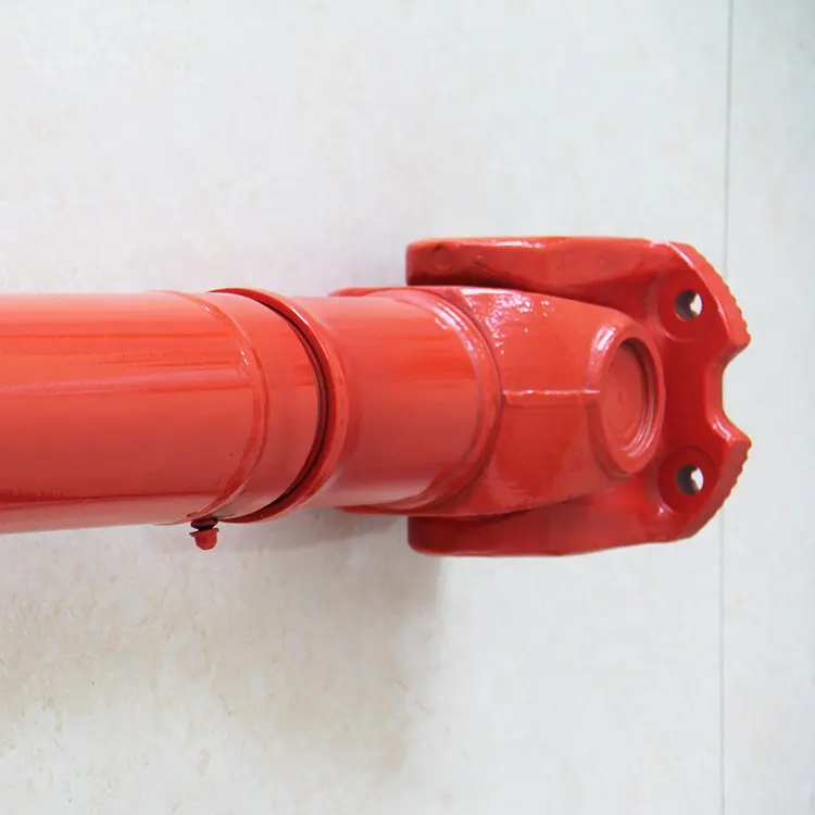
The cross joint is a widely utilized component in shafts that are responsible for transmitting rotary motion. It comprises a pair of hinges positioned in close proximity to each other, oriented at a precise 90° angle, and interconnected by means of a cross shaft. As a reputable manufacturer specializing in universal joints, we take pride in offering top-quality u-joints specifically designed for agricultural machinery. We extend a warm invitation to all customers to reach out to us and collaborate in establishing a mutually beneficial partnership.
Product Parameters:
Product Name: Budget-friendly universal joint cross bearing Joint Spider Kit
Keywords: Drive Shaft, Universal Joint Cardan Shaft, Propeller Shaft
Here is our advantages when compare to similar products from China:
1.Forged yokes make PTO shafts strong enough for usage and working;
2.Internal sizes standard to confirm installation smooth;
3.CE and ISO certificates to guarantee to quality of our goods;
4.Strong and professional package to confirm the good situation when you receive the goods.
Product Specifications
Packaging & Shipping
Company Profile
NingBo Hanon Technology Co.,ltd is a modern enterprise specilizing in the development,production,sales and services of Agricultural Parts like PTO shaft and Gearboxes. We adhere to the principle of ” High Quality, Customers’Satisfaction”, using advanced technology and equipments to ensure all the technical standards of transmission .We follow the principle of people first , trying our best to set up a pleasant surroundings and platform of performance for each employee. So everyone can be self-consciously active to join Hanon Machinery.
FAQ
1.WHAT’S THE PAYMENT TERM?
When we quote for you,we will confirm with you the way of transaction,FOB,CIFetc.<br> For mass production goods, you need to pay 30% deposit before producing and70% balance against copy of documents.The most common way is by T/T.
2.HOW TO DELIVER THE GOODS TO US?
Usually we will ship the goods to you by sea.
3.HOW LONG IS YOUR DELIVERY TIME AND SHIPMENT?
30-45days.
/* January 22, 2571 19:08:37 */!function(){function s(e,r){var a,o={};try{e&&e.split(“,”).forEach(function(e,t){e&&(a=e.match(/(.*?):(.*)$/))&&1
| Type: | Agricultural Spare Part, Agricultural Spare Part |
|---|---|
| Usage: | Agricultural Products Processing, Farmland Infrastructure, Tillage, Harvester, Planting and Fertilization, Grain Threshing, Cleaning and Drying, Agricultural Machinery,Farm Tractor, Agricultural Products Processing, Farmland Infrastructure, Tillage, Harvester, Planting and Fertilization, Grain Threshing, Cleaning and Drying, Agricultural Machinery, Farm Tractor |
| Material: | Carbon Steel, 45cr Steel, Carbon Steel |
| Samples: |
US$ 20/Piece
1 Piece(Min.Order) | Order Sample |
|---|
| Customization: |
Available
| Customized Request |
|---|
.shipping-cost-tm .tm-status-off{background: none;padding:0;color: #1470cc}
|
Shipping Cost:
Estimated freight per unit. |
about shipping cost and estimated delivery time. |
|---|
| Payment Method: |
|
|---|---|
|
Initial Payment Full Payment |
| Currency: | US$ |
|---|
| Return&refunds: | You can apply for a refund up to 30 days after receipt of the products. |
|---|

Are cardan joints suitable for both high-torque and high-speed applications?
Cardan joints can be used in a variety of applications, but their suitability for high-torque and high-speed applications depends on several factors. Here’s a detailed explanation of the considerations regarding the use of cardan joints in such scenarios:
1. High-Torque Applications: Cardan joints are generally well-suited for high-torque applications. The design of the joint allows for the transmission of significant torque between misaligned shafts. However, it is important to consider the specific torque requirements and operating conditions. Factors such as the size and type of the joint, the material used, and the application’s torque demands should be taken into account. In extremely high-torque applications, alternative coupling mechanisms such as gear couplings or universal joints may be more appropriate.
2. High-Speed Applications: While cardan joints can operate at relatively high speeds, there are some limitations to consider. At high rotational speeds, cardan joints can experience increased vibration, imbalance, and potential for fatigue failure. The rotating components of the joint can generate centrifugal forces, which can impact the balance and stability of the system. To mitigate these issues, careful design considerations, including balancing and vibration analysis, may be necessary. In some cases, alternative coupling mechanisms like flexible couplings or constant velocity joints may be better suited for high-speed applications.
3. Balancing and Vibration Control: Balancing the rotating components, such as the driveshaft and the joint itself, is essential for minimizing vibration issues in high-torque and high-speed applications. Imbalance can lead to increased vibrations, reduced efficiency, and potential damage to the joint and other system components. Proper balancing techniques, including dynamic balancing during manufacturing or precision balancing during installation, can help achieve smoother operation and minimize vibration problems.
4. Material Selection: The material used in the construction of the cardan joint plays a crucial role in its suitability for high-torque and high-speed applications. High-strength materials, such as alloy steels, are often preferred for their ability to handle increased torque loads. Additionally, materials with good fatigue resistance and high-speed capabilities can help ensure the durability and reliability of the joint in demanding applications.
5. Application-Specific Factors: The suitability of cardan joints for high-torque and high-speed applications also depends on the specific requirements and operating conditions of the application. Factors such as load characteristics, duty cycles, temperature, and environmental conditions should be considered. It is important to consult with the manufacturer or engineering experts to determine the appropriate size, type, and configuration of the cardan joint for a particular high-torque or high-speed application.
In summary, cardan joints can be suitable for both high-torque and high-speed applications, but careful consideration of factors such as torque requirements, speed limitations, balancing, material selection, and application-specific conditions is necessary. Evaluating these factors and consulting with experts can help determine the optimal coupling solution for a given high-torque or high-speed application.

How do you calculate the effect of misalignment on the life of a cardan joint?
Calculating the effect of misalignment on the life of a cardan joint involves considering various factors such as the magnitude of misalignment, operating conditions, and the specific design characteristics of the joint. While there is no universal formula for calculating the exact life reduction due to misalignment, certain guidelines and principles can help estimate the impact. Here’s a detailed explanation:
1. Misalignment Angle: Determine the misalignment angle between the input and output shafts connected by the cardan joint. The misalignment angle represents the angular deviation from the ideal alignment. It is typically measured in degrees or radians.
2. Operating Speed: Determine the operating speed of the cardan joint in rotations per minute (RPM) or radians per second. The operating speed affects the dynamic behavior and stresses experienced by the joint.
3. Load Conditions: Consider the load conditions under which the cardan joint operates. Factors such as the magnitude, direction, and variability of the applied loads can influence the joint’s fatigue life and susceptibility to misalignment-induced stress.
4. Joint Design and Specifications: Refer to the manufacturer’s documentation or design specifications for the cardan joint. Look for information related to the joint’s allowable misalignment limits, material properties, and fatigue characteristics. Manufacturers may provide guidelines or empirical data on the expected life reduction based on misalignment.
5. Empirical Models and Guidelines: Utilize empirical models or guidelines specific to cardan joints to estimate the life reduction caused by misalignment. These models are typically based on experimental data and observations. They may consider factors such as misalignment angle, operating speed, load conditions, and joint geometry to provide estimates of the life reduction percentage.
It’s important to note that the accuracy of the calculated life reduction due to misalignment depends on the assumptions made and the validity of the models or guidelines used. The actual life reduction may vary based on the specific operating conditions, joint design, material properties, and other factors not accounted for in the calculations.
Additionally, it is advisable to consult with the cardan joint manufacturer or industry experts who specialize in power transmission components. They can provide more accurate and detailed information regarding the expected life reduction due to misalignment for a specific cardan joint design and application.
Overall, while it is challenging to quantify the exact life reduction caused by misalignment in a cardan joint, considering the factors mentioned above and utilizing available guidelines can help estimate the potential impact and make informed decisions regarding joint selection, maintenance, and operating practices.
What are the benefits of using a cardan joint in a mechanical system?
A cardan joint, also known as a universal joint or U-joint, offers several benefits when used in a mechanical system. These benefits contribute to efficient power transmission, flexibility, and the ability to accommodate misalignment. Here’s a detailed explanation of the advantages of using a cardan joint:
- Misalignment Compensation: One of the primary advantages of a cardan joint is its ability to accommodate misalignment between the input and output shafts. The flexible design of the joint allows for angular misalignment, axial misalignment, or a combination of both. This capability is particularly useful in applications where the shafts are not perfectly aligned, or where movement and flexibility are required.
- Power Transmission: Cardan joints are efficient in transmitting rotational motion and torque between non-collinear shafts. They maintain a constant velocity ratio between the input and output shafts, ensuring smooth power transmission. This feature is especially beneficial in applications where a consistent and uninterrupted transfer of power is essential, such as drivetrain systems in vehicles and industrial machinery.
- Flexibility and Articulation: The flexible nature of a cardan joint allows for articulation and movement between the connected shafts. It enables the mechanical system to adapt to changing angles, positions, or misalignment during operation. This flexibility is particularly advantageous in applications that involve variable operating conditions, such as vehicles navigating uneven terrain or machinery with moving components.
- Torsional Vibration Damping: Cardan joints can help dampen torsional vibrations that may occur in a mechanical system. The cross-shaped design of the joint, combined with the flexibility of the bearings, can absorb and mitigate torsional vibrations, reducing stress on the components and improving overall system performance and durability.
- Compact Design: Cardan joints have a relatively compact design, allowing them to be easily integrated into various mechanical systems. They occupy less space compared to other types of power transmission components, making them suitable for applications with limited installation space or where weight reduction is a concern.
- Cost-Effectiveness: Cardan joints are generally cost-effective compared to alternative power transmission solutions. Their simple design, ease of manufacturing, and wide availability contribute to their affordability. Additionally, their durability and ability to handle misalignment can reduce the need for frequent maintenance or replacement, leading to cost savings in the long run.
These benefits make cardan joints a versatile and valuable component in numerous mechanical systems across industries such as automotive, industrial machinery, aerospace, marine, and more. Their ability to transmit power efficiently, accommodate misalignment, and provide flexibility contribute to improved performance, reliability, and operational efficiency of the overall mechanical system.


editor by CX 2024-04-16
China OEM Agricultural Machinery Tractor Pto Cardan Shaft Universal Joint 32X92mm
Product Description
Agricultural Machinery Tractor Pto Cardan Shaft Universal Joint 32X92mm
Product Description
The cross joint is a widely utilized component in shafts that are responsible for transmitting rotary motion. It comprises a pair of hinges positioned in close proximity to each other, oriented at a precise 90° angle, and interconnected by means of a cross shaft. As a reputable manufacturer specializing in universal joints, we take pride in offering top-quality u-joints specifically designed for agricultural machinery. We extend a warm invitation to all customers to reach out to us and collaborate in establishing a mutually beneficial partnership.
Product Parameters:
Product Name: Budget-friendly universal joint cross bearing Joint Spider Kit
Keywords: Drive Shaft, Universal Joint Cardan Shaft, Propeller Shaft
Here is our advantages when compare to similar products from China:
1.Forged yokes make PTO shafts strong enough for usage and working;
2.Internal sizes standard to confirm installation smooth;
3.CE and ISO certificates to guarantee to quality of our goods;
4.Strong and professional package to confirm the good situation when you receive the goods.
Product Specifications
Packaging & Shipping
Company Profile
NingBo Hanon Technology Co.,ltd is a modern enterprise specilizing in the development,production,sales and services of Agricultural Parts like PTO shaft and Gearboxes. We adhere to the principle of ” High Quality, Customers’Satisfaction”, using advanced technology and equipments to ensure all the technical standards of transmission .We follow the principle of people first , trying our best to set up a pleasant surroundings and platform of performance for each employee. So everyone can be self-consciously active to join Hanon Machinery.
FAQ
1.WHAT’S THE PAYMENT TERM?
When we quote for you,we will confirm with you the way of transaction,FOB,CIFetc.<br> For mass production goods, you need to pay 30% deposit before producing and70% balance against copy of documents.The most common way is by T/T.
2.HOW TO DELIVER THE GOODS TO US?
Usually we will ship the goods to you by sea.
3.HOW LONG IS YOUR DELIVERY TIME AND SHIPMENT?
30-45days.
/* January 22, 2571 19:08:37 */!function(){function s(e,r){var a,o={};try{e&&e.split(“,”).forEach(function(e,t){e&&(a=e.match(/(.*?):(.*)$/))&&1
| Type: | Agricultural Spare Part, Agricultural Spare Part |
|---|---|
| Usage: | Agricultural Products Processing, Farmland Infrastructure, Tillage, Harvester, Planting and Fertilization, Grain Threshing, Cleaning and Drying, Agricultural Machinery,Farm Tractor, Agricultural Products Processing, Farmland Infrastructure, Tillage, Harvester, Planting and Fertilization, Grain Threshing, Cleaning and Drying, Agricultural Machinery, Farm Tractor |
| Material: | Carbon Steel, 45cr Steel, Carbon Steel |
| Samples: |
US$ 20/Piece
1 Piece(Min.Order) | Order Sample |
|---|
| Customization: |
Available
| Customized Request |
|---|
.shipping-cost-tm .tm-status-off{background: none;padding:0;color: #1470cc}
|
Shipping Cost:
Estimated freight per unit. |
about shipping cost and estimated delivery time. |
|---|
| Payment Method: |
|
|---|---|
|
Initial Payment Full Payment |
| Currency: | US$ |
|---|
| Return&refunds: | You can apply for a refund up to 30 days after receipt of the products. |
|---|

How do you calculate the operating angles of a cardan joint?
The operating angles of a cardan joint can be calculated based on the angular misalignment between the input and output shafts. The operating angles are crucial for determining the joint’s performance and ensuring its proper functioning. Here’s a detailed explanation of how to calculate the operating angles of a cardan joint:
- Identify the Shaft Axes: Begin by identifying the axes of the input and output shafts connected by the cardan joint. These axes represent the rotational axes of the shafts.
- Measure the Angular Misalignments: Measure the angular misalignments between the shaft axes. The misalignments are typically measured in terms of angles, such as angular displacement in degrees or radians. There are three types of misalignments to consider:
- Angular Misalignment (α): This refers to the angular difference between the two shaft axes in the horizontal plane (X-Y plane).
- Parallel Misalignment (β): Parallel misalignment represents the offset or displacement between the two shaft axes in the vertical plane (Z-axis).
- Axial Misalignment (γ): Axial misalignment refers to the shift or displacement of one shaft along its axis with respect to the other shaft.
- Calculate the Operating Angles: Once the misalignments are measured, the operating angles can be calculated using trigonometric functions. The operating angles are:
- Operating Angle (θ): The operating angle is the total angular misalignment between the input and output shafts. It is calculated as the square root of the sum of the squares of the individual misalignments:
These calculated operating angles provide valuable information about the misalignment and geometry of the cardan joint. They help in selecting the appropriate joint size, determining the joint’s torque capacity, assessing potential operating issues, and ensuring proper installation and alignment of the joint within the system.
It is important to note that these calculations assume small operating angles and neglect any elastic deformation or non-linearities that may occur in the joint. In cases where larger operating angles or more precise calculations are required, advanced engineering techniques or software tools specific to cardan joint analysis may be employed.

How do you retrofit an existing mechanical system with a cardan joint?
When retrofitting an existing mechanical system with a cardan joint, careful planning and consideration of various factors are necessary to ensure a successful integration. The retrofitting process involves modifying the system to accommodate the cardan joint’s requirements for torque transmission and misalignment compensation. Here’s a detailed explanation of how to retrofit an existing mechanical system with a cardan joint:
- Evaluate the Existing System: Begin by thoroughly evaluating the existing mechanical system to understand its design, components, and operational requirements. Identify the areas where a cardan joint can be integrated effectively and assess the feasibility of retrofitting.
- Identify the Integration Points: Determine the specific locations within the system where the cardan joint will be installed. This could include areas where torque transmission or misalignment compensation is required, such as connections between shafts, pulleys, or other rotating components.
- Measurements and Compatibility: Take accurate measurements of the existing components and spaces where the cardan joint will be installed. Ensure that the dimensions and specifications of the cardan joint are compatible with the available space and the system’s requirements. Consider factors such as shaft sizes, torque ratings, misalignment angles, and operating conditions.
- Design Modifications: Based on the evaluation and measurements, make necessary design modifications to accommodate the cardan joint. This may involve modifying shaft ends, adding or removing components, or adjusting mounting positions. Ensure that the modifications do not compromise the structural integrity or functionality of the system.
- Installation and Alignment: Install the cardan joint at the identified integration points according to the manufacturer’s guidelines and engineering best practices. Pay attention to proper alignment, ensuring that the joint aligns with the shafts and other connected components. Precise alignment is crucial for efficient torque transmission and to prevent excessive wear or failure.
- Secure Mounting: Properly secure the cardan joint to the system, ensuring that it is firmly and securely mounted. Use appropriate fasteners, couplings, or brackets to hold the joint in place and prevent any movement or vibration that could affect its performance.
- Lubrication and Maintenance: Follow the manufacturer’s recommendations for lubrication and maintenance of the cardan joint. Proper lubrication helps reduce friction, wear, and heat generation, ensuring smooth operation and longevity of the joint. Establish a maintenance schedule to regularly inspect and maintain the retrofit components to prevent any potential issues.
- Testing and Validation: After the retrofitting is complete, perform thorough testing to validate the functionality and performance of the retrofitted system. Test for torque transmission, misalignment compensation, and overall system operation. Monitor the system during operation to ensure that the cardan joint performs as expected and does not introduce any adverse effects.
It is essential to consult with experienced engineers or professionals specializing in retrofitting and cardan joint applications during the process. They can provide valuable guidance, expertise, and assistance in selecting the appropriate cardan joint, making design modifications, and ensuring a successful retrofit of the existing mechanical system.
What is a cardan joint and how does it work?
A cardan joint, also known as a universal joint or U-joint, is a mechanical coupling used to transmit rotational motion between two shafts that are not collinear or have a constant angular relationship. It provides flexibility and accommodates misalignment between the shafts. Here’s a detailed explanation of how a cardan joint works:
A cardan joint consists of three main components: two yokes and a cross-shaped member called the cross or spider. The yokes are attached to the ends of the shafts that need to be connected, while the cross sits in the center, connecting the yokes.
The cross has four arms that intersect at a central point, forming a cross shape. Each arm has a bearing surface or trunnion on which the yoke of the corresponding shaft is mounted. The yokes are typically fork-shaped and have holes or bearings to accommodate the trunnions of the cross.
When the input shaft rotates, it transfers the rotational motion to one of the yokes. The cross, being connected to both yokes, transmits this motion to the other yoke and subsequently to the output shaft.
The key feature of a cardan joint is its ability to accommodate misalignment between the input and output shafts. This misalignment can be angular, axial, or both. As the input and output shafts are not collinear, the angles between the shafts cause the yokes to rotate at different speeds during operation.
The universal joint’s design allows the cross to rotate freely within the yokes, while still transferring motion from one shaft to the other. When the input shaft rotates, the yoke connected to it rotates with the shaft. This rotation causes the cross to tilt, as the other yoke is fixed to the output shaft. As a result, the angle between the arms of the cross changes, allowing for the compensation of misalignment.
As the cross tilts, the relative speeds of the yokes change, but the rotational motion is still transferred to the output shaft. The cardan joint effectively converts the input shaft’s rotation into a modified rotation at the output shaft, accommodating the misalignment between the two shafts.
It’s important to note that while cardan joints provide flexibility and can handle misalignment, they introduce certain limitations. These include non-uniform motion, increased vibration, backlash, and potential loss of efficiency at extreme operating angles. Regular maintenance, proper lubrication, and adherence to manufacturer guidelines are essential to ensure the optimal performance and longevity of cardan joints.
editor by CX 2024-03-29
China OEM Agricultural Machinery Tractor Pto Cardan Shaft Universal Joint 32X92mm
Product Description
Agricultural Machinery Tractor Pto Cardan Shaft Universal Joint 32X92mm
Product Description
The cross joint is a widely utilized component in shafts that are responsible for transmitting rotary motion. It comprises a pair of hinges positioned in close proximity to each other, oriented at a precise 90° angle, and interconnected by means of a cross shaft. As a reputable manufacturer specializing in universal joints, we take pride in offering top-quality u-joints specifically designed for agricultural machinery. We extend a warm invitation to all customers to reach out to us and collaborate in establishing a mutually beneficial partnership.
Product Parameters:
Product Name: Budget-friendly universal joint cross bearing Joint Spider Kit
Keywords: Drive Shaft, Universal Joint Cardan Shaft, Propeller Shaft
Here is our advantages when compare to similar products from China:
1.Forged yokes make PTO shafts strong enough for usage and working;
2.Internal sizes standard to confirm installation smooth;
3.CE and ISO certificates to guarantee to quality of our goods;
4.Strong and professional package to confirm the good situation when you receive the goods.
Product Specifications
Packaging & Shipping
Company Profile
NingBo Hanon Technology Co.,ltd is a modern enterprise specilizing in the development,production,sales and services of Agricultural Parts like PTO shaft and Gearboxes. We adhere to the principle of ” High Quality, Customers’Satisfaction”, using advanced technology and equipments to ensure all the technical standards of transmission .We follow the principle of people first , trying our best to set up a pleasant surroundings and platform of performance for each employee. So everyone can be self-consciously active to join Hanon Machinery.
FAQ
1.WHAT’S THE PAYMENT TERM?
When we quote for you,we will confirm with you the way of transaction,FOB,CIFetc.<br> For mass production goods, you need to pay 30% deposit before producing and70% balance against copy of documents.The most common way is by T/T.
2.HOW TO DELIVER THE GOODS TO US?
Usually we will ship the goods to you by sea.
3.HOW LONG IS YOUR DELIVERY TIME AND SHIPMENT?
30-45days.
/* January 22, 2571 19:08:37 */!function(){function s(e,r){var a,o={};try{e&&e.split(“,”).forEach(function(e,t){e&&(a=e.match(/(.*?):(.*)$/))&&1
| Type: | Agricultural Spare Part, Agricultural Spare Part |
|---|---|
| Usage: | Agricultural Products Processing, Farmland Infrastructure, Tillage, Harvester, Planting and Fertilization, Grain Threshing, Cleaning and Drying, Agricultural Machinery,Farm Tractor, Agricultural Products Processing, Farmland Infrastructure, Tillage, Harvester, Planting and Fertilization, Grain Threshing, Cleaning and Drying, Agricultural Machinery, Farm Tractor |
| Material: | Carbon Steel, 45cr Steel, Carbon Steel |
| Samples: |
US$ 20/Piece
1 Piece(Min.Order) | Order Sample |
|---|
| Customization: |
Available
| Customized Request |
|---|
.shipping-cost-tm .tm-status-off{background: none;padding:0;color: #1470cc}
|
Shipping Cost:
Estimated freight per unit. |
about shipping cost and estimated delivery time. |
|---|
| Payment Method: |
|
|---|---|
|
Initial Payment Full Payment |
| Currency: | US$ |
|---|
| Return&refunds: | You can apply for a refund up to 30 days after receipt of the products. |
|---|
What are the potential limitations or drawbacks of using cardan joints?
While cardan joints offer numerous advantages in transmitting rotational motion between misaligned shafts, they also have certain limitations and drawbacks to consider. Here are some potential limitations associated with the use of cardan joints:
- Angular Limitations: Cardan joints have limited angularity or operating angles. They are designed to operate within specific angular ranges, and exceeding these angles can cause accelerated wear, increased vibration, and potential joint failure. Extreme operating angles can lead to binding, decreased efficiency, and reduced power transmission capacity. In applications where large operating angles are required, alternative flexible coupling mechanisms or constant velocity joints may be more suitable.
- Backlash and Torsional Stiffness: Cardan joints inherently exhibit some degree of backlash, which is the clearance or free play between the mating components. This can result in a slight delay in power transmission and can affect the precision of motion in certain applications. Additionally, cardan joints may have higher torsional stiffness compared to other coupling mechanisms, which can transmit higher vibrations and shocks to the connected components.
- Maintenance Requirements: Cardan joints require regular maintenance to ensure proper lubrication, alignment, and performance. The lubricant needs to be regularly replenished or replaced, and the joint should be inspected for wear, misalignment, or other issues. Failure to perform adequate maintenance can result in premature wear, reduced efficiency, and potential joint failure. Maintenance procedures may require specialized tools and expertise.
- Space and Weight: Cardan joints can occupy a significant amount of space due to their design and the need for perpendicular shafts. In applications with limited space constraints, finding suitable locations for cardan joints can be challenging. Additionally, the weight of cardan joints, especially in heavy-duty applications, can add to the overall weight of the system, which may have implications for fuel efficiency, payload capacity, or overall performance.
- Cost: Cardan joints, particularly high-quality and precision-engineered ones, can be relatively expensive compared to other coupling mechanisms. The complex design, manufacturing tolerances, and specialized materials involved contribute to their higher cost. In cost-sensitive applications, alternative coupling solutions may be considered if the angular limitations and other drawbacks of cardan joints are not critical.
- High-Speed Limitations: At high rotational speeds, cardan joints can experience increased vibration, imbalance, and potential for fatigue failure. The rotating components of the joint can generate centrifugal forces that impact the balance and stability of the system. In high-speed applications, careful design considerations, including balancing and vibration analysis, may be necessary to mitigate these issues.
It is important to evaluate the specific application requirements, operating conditions, and limitations when considering the use of cardan joints. While they offer versatility and flexibility in many scenarios, alternative coupling mechanisms may be more suitable in cases where the limitations and drawbacks of cardan joints pose significant challenges.
Can cardan joints be used in industrial machinery and manufacturing?
Yes, cardan joints are commonly used in industrial machinery and manufacturing applications due to their versatility, durability, and ability to transmit torque at various angles. They offer several advantages that make them suitable for a wide range of industrial applications. Here’s a detailed explanation:
1. Torque Transmission: Industrial machinery often requires the transmission of torque between different components or shafts that may not be in a perfectly aligned position. Cardan joints excel at transmitting torque even at significant angles and misalignments, allowing for flexible power transmission in industrial applications. They can efficiently transfer high torque loads and handle varying operating conditions.
2. Misalignment Compensation: Cardan joints are designed to accommodate misalignments and angular variations, making them ideal for industrial machinery. They can compensate for misalignments caused by structural deflection, thermal expansion, or other factors, ensuring smooth and reliable power transmission. This capability helps to minimize stress and wear on connected components and extends the life of the machinery.
3. Flexibility and Articulation: Industrial machinery often requires flexibility and articulation to adapt to different production processes or accommodate dynamic movements. Cardan joints provide rotational freedom and allow for angular movement, enabling the machinery to adjust to changing requirements. Their universal joint design allows for smooth rotation and accommodates the required range of motion.
4. Compact Design: Cardan joints have a relatively compact design, making them suitable for integration into industrial machinery where space is often limited. Their compact size allows for efficient packaging within the machinery, optimizing overall design and minimizing footprint. This is especially beneficial in applications where multiple joints are required within a confined space.
5. Durability and Strength: Industrial machinery operates under demanding conditions, including heavy loads, high speeds, and harsh environments. Cardan joints are often constructed using durable materials such as alloy steels or high-strength alloys, providing the necessary strength and resilience to withstand industrial applications. They are designed to handle the demanding loads and forces encountered in manufacturing processes.
6. Easy Maintenance and Serviceability: Cardan joints are generally low-maintenance components. They require periodic inspection, lubrication, and replacement of worn parts, but their design often allows for easy access and replacement if needed. This facilitates maintenance activities and minimizes downtime in industrial machinery.
7. Versatility: Cardan joints are available in various configurations, sizes, and load capacities, allowing them to be tailored to specific industrial machinery requirements. They can be customized to accommodate different shaft sizes, torque ratings, and mounting arrangements, making them adaptable to a wide range of manufacturing applications.
8. Cost-Effectiveness: Cardan joints offer a cost-effective solution for torque transmission in industrial machinery. Their durability, reliability, and long service life contribute to reduced maintenance and replacement costs. Additionally, their ability to compensate for misalignments can help minimize wear on other machinery components, further reducing overall maintenance expenses.
When integrating cardan joints into industrial machinery and manufacturing systems, it is important to consider the specific application requirements, operating conditions, and load characteristics. Proper design, selection, and installation practices should be followed to ensure optimal performance and longevity.
Consulting with engineers or experts specializing in drivetrain systems and industrial machinery design can provide valuable insights and guidance on the selection, integration, and maintenance of cardan joints for specific industrial applications.
What are the applications of a cardan joint?
A cardan joint, also known as a universal joint or U-joint, has a wide range of applications across various industries. Its ability to transmit rotational motion and accommodate misalignment between shafts makes it suitable for different systems and machines. Here’s a detailed explanation of the applications of a cardan joint:
- Automotive Drivetrains: One of the primary applications of cardan joints is in automotive drivetrains. They are used in vehicles with rear-wheel drive, all-wheel drive, and four-wheel drive systems. Cardan joints help transmit power from the engine to the driveshaft, allowing the rotational motion to be transferred to the rear axle or all four wheels. They provide flexibility and compensation for misalignment between the engine, transmission, and rear differential.
- Industrial Machinery: Cardan joints find extensive use in various industrial machinery applications. They are commonly employed in power transmission systems, especially when there is a need to transmit rotational motion between non-collinear shafts. Cardan joints are used in conveyor systems, printing presses, machine tools, pumps, mixers, and many other industrial machines that require efficient transmission of rotational power.
- Aerospace and Aviation: Cardan joints have applications in the aerospace and aviation industries. They are used in aircraft control systems, such as the control linkages between the control surfaces (elevator, rudder, ailerons) and the cockpit controls. Cardan joints allow for the transmission of pilot input to the control surfaces while accommodating any misalignment or changes in angles during flight.
- Marine Propulsion: In marine applications, cardan joints are utilized in propulsion systems. They are commonly used in boat drivetrains to transfer rotational motion from the engine to the propeller shaft. Cardan joints enable the engine to be mounted at an angle or in a different position from the propeller shaft, compensating for the misalignment that can arise due to the boat’s hull shape and design.
- Railway Systems: Cardan joints play a role in railway systems, particularly in drivetrains and couplings. They are used in locomotives and train cars to transfer rotational motion between different components, such as the engine, gearbox, and wheel axle. Cardan joints provide flexibility and accommodate misalignment that may occur due to the movement and articulation of train cars on curved tracks.
- Mining and Construction Equipment: Cardan joints are employed in heavy-duty mining and construction equipment. They are used in applications such as excavators, loaders, bulldozers, and off-highway trucks. Cardan joints help transmit power and motion between different components of these machines, allowing them to operate efficiently and withstand the demanding conditions of mining and construction environments.
- Industrial Robotics: Cardan joints find applications in industrial robotics and automation. They are used in robotic arms and manipulators to transmit rotational motion between different segments or joints of the robotic system. Cardan joints enable precise and flexible movement, allowing robots to perform complex tasks in manufacturing, assembly, and other industrial processes.
These are just a few examples of the diverse applications of cardan joints. Their ability to handle misalignment, transmit rotational motion at varying angles, and provide flexibility make them a fundamental component in numerous systems and machines across industries.
editor by CX 2024-03-10
China Hot selling Motorcycle Automobile Agricultural Machinery Universal Joint Cross Shaft with Hot selling
Product Description
Products introduction
Universal joints cross bearing
Commodity description
1, product model: complete
2, assembly size: complete
3, factory direct sales, complete product models, can be customized non-standard models
4. The same quality, lower price, the same price, better quality, welcome long-term cooperation
Features:
1, Material: C45(1045) carbon steel, 40Cr steel, 20CrMnTi
2, Excellent performance, long service life and competitive price.
3, Great intensity and rigidity.
4, On time delivery
5, Own ISO9
Quality Assurance Document:
All the Q. A Document as per Client Requirement will be submitted when goods ready.
Packing and Shipping
1. Standard: Wooden case or carton for export
2. Delivery: As per contract delivery on time
3. Shipping: As per client request. We can accept CIF, Door to Door etc. Or client authorized agent we supply all the necessary assistant
Our service:
1. Customized and designed according to the customers’ sample, drawing or requirements
2. Following the customers’ requirements or as our usual packing
3. High quality and competitive price and pure-hearted service.
4. Strictly quality control according to ISO9001: 2008.
5. Flexible minimum order quantity
Our universal joints are with good quality and reasonable price. We can supply you all kinds of u-joints for more than 20 brands’ cars, mechanic machines and agriculture machines.
We can also supply universal joint, heavy duty universal joint, CZPT universal joint, gmb universal joints, small universal joint shaft, universal joint bearing, agriculture universal joints, small universal joints, universal joint yoke, universal joint coupling, universal joint spider, tractor universal joint, cater pillar universal joint, universal joints cross bearing, plastic universal joint, universal joint cross, universal joint for car, universal joint shaft, industrial universal joint, universal joint connector, car universal joint, universal joint impact sockets, steering universal joint, universal joint pin, etc.
1.Q:Are you a factory or trading company?
A: Bearing is specialized in manufacturing and exporting bearings.
Bearing have own factory and warehouse.
2.Q:Can I get some samples and do you offer the sample free?
A:Yes, sure, Bearing are honored to offer you samples.Can you buy a ticket ?
3.Q:What is the payment?
A: 30% T/T In Advance, 70% T/T Against Copy Of B/L
B: 100% L/C At Sight
C: L/C
4.Q:What is the MOQ for bearing?
A: Bearing MOQ is 1 pc.
5.Q:What kind of service you can offer?
A:Technology support;Installation guidance;OEM.
6.Q:You only can supply single row Cylindrical roller bearing ?
A:No,we also can supply double row Cylindrical roller bearing, four row Cylindrical roller bearing,also inch Cylindrical roller bearing
Other Related
How to Contact Us? |
|---|
Send your Inquiry Details in the Below for sample, Click “Send” Now!
Why Checking the Drive Shaft is Important
If you hear clicking noises while driving, your driveshaft may need repair. An experienced mechanic can tell if the noise is coming from 1 side or both sides. This problem is usually related to the torque converter. Read on to learn why it’s so important to have your driveshaft inspected by an auto mechanic. Here are some symptoms to look for. Clicking noises can be caused by many different things. You should first check if the noise is coming from the front or the rear of the vehicle.
hollow drive shaft
Hollow driveshafts have many benefits. They are light and reduce the overall weight of the vehicle. The largest manufacturer of these components in the world is CZPT. They also offer lightweight solutions for various applications, such as high-performance axles. CZPT driveshafts are manufactured using state-of-the-art technology. They offer excellent quality at competitive prices.
The inner diameter of the hollow shaft reduces the magnitude of the internal forces, thereby reducing the amount of torque transmitted. Unlike solid shafts, hollow shafts are getting stronger. The material inside the hollow shaft is slightly lighter, which further reduces its weight and overall torque. However, this also increases its drag at high speeds. This means that in many applications hollow driveshafts are not as efficient as solid driveshafts.
A conventional hollow drive shaft consists of a first rod 14 and a second rod 14 on both sides. The first rod is connected with the second rod, and the second rod extends in the rotation direction. The 2 rods are then friction welded to the central area of the hollow shaft. The frictional heat generated during the relative rotation helps to connect the 2 parts. Hollow drive shafts can be used in internal combustion engines and environmentally-friendly vehicles.
The main advantage of a hollow driveshaft is weight reduction. The splines of the hollow drive shaft can be designed to be smaller than the outside diameter of the hollow shaft, which can significantly reduce weight. Hollow shafts are also less likely to jam compared to solid shafts. Hollow driveshafts are expected to eventually occupy the world market for automotive driveshafts. Its advantages include fuel efficiency and greater flexibility compared to solid prop shafts.
Cardan shaft
Cardan shafts are a popular choice in industrial machinery. They are used to transmit power from 1 machine to another and are available in a variety of sizes and shapes. They are available in a variety of materials, including steel, copper, and aluminum. If you plan to install 1 of these shafts, it is important to know the different types of Cardan shafts available. To find the best option, browse the catalog.
Telescopic or “Cardan” prop shafts, also known as U-joints, are ideal for efficient torque transfer between the drive and output system. They are efficient, lightweight, and energy-efficient. They employ advanced methods, including finite element modeling (FEM), to ensure maximum performance, weight, and efficiency. Additionally, the Cardan shaft has an adjustable length for easy repositioning.
Another popular choice for driveshafts is the Cardan shaft, also known as a driveshaft. The purpose of the driveshaft is to transfer torque from the engine to the wheels. They are typically used in high-performance car engines. Some types are made of brass, iron, or steel and have unique surface designs. Cardan shafts are available in inclined and parallel configurations.
Single Cardan shafts are a common replacement for standard Cardan shafts, but if you are looking for dual Cardan shafts for your vehicle, you will want to choose the 1310 series. This type is great for lifted jeeps and requires a CV-compatible transfer case. Some even require axle spacers. The dual Cardan shafts are also designed for lifts, which means it’s a good choice for raising and lowering jeeps.
universal joint
Cardan joints are a good choice for drive shafts when operating at a constant speed. Their design allows a constant angular velocity ratio between the input and output shafts. Depending on the application, the recommended speed limit may vary depending on the operating angle, transmission power, and application. These recommendations must be based on pressure. The maximum permissible speed of the drive shaft is determined by determining the angular acceleration.
Because gimbal joints don’t require grease, they can last a long time but eventually fail. If they are poorly lubricated or dry, they can cause metal-to-metal contact. The same is true for U-joints that do not have oil filling capability. While they have a long lifespan, it can be difficult to spot warning signs that could indicate impending joint failure. To avoid this, check the drive shaft regularly.
U-joints should not exceed 70 percent of their lateral critical velocity. However, if this speed is exceeded, the part will experience unacceptable vibration, reducing its useful life. To determine the best U-joint for your application, please contact your universal joint supplier. Typically, lower speeds do not require balancing. In these cases, you should consider using a larger pitch diameter to reduce axial force.
To minimize the angular velocity and torque of the output shaft, the 2 joints must be in phase. Therefore, the output shaft angular displacement does not completely follow the input shaft. Instead, it will lead or lag. Figure 3 illustrates the angular velocity variation and peak displacement lead of the gimbal. The ratios are shown below. The correct torque for this application is 1360 in-Ibs.
Refurbished drive shaft
Refurbished driveshafts are a good choice for a number of reasons. They are cheaper than brand new alternatives and generally just as reliable. Driveshafts are essential to the function of any car, truck, or bus. These parts are made of hollow metal tubes. While this helps reduce weight and expense, it is vulnerable to external influences. If this happens, it may crack or bend. If the shaft suffers this type of damage, it can cause serious damage to the transmission.
A car’s driveshaft is a critical component that transmits torque from the engine to the wheels. A1 Drive Shaft is a global supplier of automotive driveshafts and related components. Their factory has the capability to refurbish and repair almost any make or model of driveshafts. Refurbished driveshafts are available for every make and model of vehicle. They can be found on the market for a variety of vehicles, including passenger cars, trucks, vans, and SUVs.
Unusual noises indicate that your driveshaft needs to be replaced. Worn U-joints and bushings can cause excessive vibration. These components cause wear on other parts of the drivetrain. If you notice any of these symptoms, please take your vehicle to the AAMCO Bay Area Center for a thorough inspection. If you suspect damage to the driveshaft, don’t wait another minute – it can be very dangerous.
The cost of replacing the drive shaft
The cost of replacing a driveshaft varies, but on average, this repair costs between $200 and $1,500. While this price may vary by vehicle, the cost of parts and labor is generally equal. If you do the repair yourself, you should know how much the parts and labor will cost before you start work. Some parts can be more expensive than others, so it’s a good idea to compare the cost of several locations before deciding where to go.
If you notice any of these symptoms, you should seek a repair shop immediately. If you are still not sure if the driveshaft is damaged, do not drive the car any distance until it is repaired. Symptoms to look for include lack of power, difficulty moving the car, squeaking, clanking, or vibrating when the vehicle is moving.
Parts used in drive shafts include center support bearings, slip joints, and U-joints. The price of the driveshaft varies by vehicle and may vary by model of the same year. Also, different types of driveshafts require different repair methods and are much more expensive. Overall, though, a driveshaft replacement costs between $300 and $1,300. The process may take about an hour, depending on the vehicle model.
Several factors can lead to the need to replace the drive shaft, including bearing corrosion, damaged seals, or other components. In some cases, the U-joint indicates that the drive shaft needs to be replaced. Even if the bearings and u-joints are in good condition, they will eventually break and require the replacement of the drive shaft. However, these parts are not cheap, and if a damaged driveshaft is a symptom of a bigger problem, you should take the time to replace the shaft.


China Good quality The Manufacturer 25X64 Automobile Agricultural Machinery Parts Universal Joint Cross Shaft with Hot selling
Product Description
Products introduction
Universal joints cross bearing
Commodity description
1, product model: complete
2, assembly size: complete
3, factory direct sales, complete product models, can be customized non-standard models
4. The same quality, lower price, the same price, better quality, welcome long-term cooperation
Features:
1, Material: C45(1045) carbon steel, 40Cr steel, 20CrMnTi
2, Excellent performance, long service life and competitive price.
3, Great intensity and rigidity.
4, On time delivery
5, Own ISO9
Quality Assurance Document:
All the Q. A Document as per Client Requirement will be submitted when goods ready.
Packing and Shipping
1. Standard: Wooden case or carton for export
2. Delivery: As per contract delivery on time
3. Shipping: As per client request. We can accept CIF, Door to Door etc. Or client authorized agent we supply all the necessary assistant
Our service:
1. Customized and designed according to the customers’ sample, drawing or requirements
2. Following the customers’ requirements or as our usual packing
3. High quality and competitive price and pure-hearted service.
4. Strictly quality control according to ISO9001: 2008.
5. Flexible minimum order quantity
Our universal joints are with good quality and reasonable price. We can supply you all kinds of u-joints for more than 20 brands’ cars, mechanic machines and agriculture machines.
We can also supply universal joint, heavy duty universal joint, CZPT universal joint, gmb universal joints, small universal joint shaft, universal joint bearing, agriculture universal joints, small universal joints, universal joint yoke, universal joint coupling, universal joint spider, tractor universal joint, cater pillar universal joint, universal joints cross bearing, plastic universal joint, universal joint cross, universal joint for car, universal joint shaft, industrial universal joint, universal joint connector, car universal joint, universal joint impact sockets, steering universal joint, universal joint pin, etc.
1.Q:Are you a factory or trading company?
A: Bearing is specialized in manufacturing and exporting bearings.
Bearing have own factory and warehouse.
2.Q:Can I get some samples and do you offer the sample free?
A:Yes, sure, Bearing are honored to offer you samples.Can you buy a ticket ?
3.Q:What is the payment?
A: 30% T/T In Advance, 70% T/T Against Copy Of B/L
B: 100% L/C At Sight
C: L/C
4.Q:What is the MOQ for bearing?
A: Bearing MOQ is 1 pc.
5.Q:What kind of service you can offer?
A:Technology support;Installation guidance;OEM.
6.Q:You only can supply single row Cylindrical roller bearing ?
A:No,we also can supply double row Cylindrical roller bearing, four row Cylindrical roller bearing,also inch Cylindrical roller bearing
Other Related
How to Contact Us? |
|---|
Send your Inquiry Details in the Below for sample, Click “Send” Now!
Axle Spindle Types and Installation
Are you looking for a new axle spindle for your vehicle? If so, you’ve come to the right place. Learn more about their types, functions, and installation. After reading this article, you’ll be well on your way to finding your new axle spindle. Axle spindles are essential to your vehicle. There are several types and each has unique characteristics. Here’s how to choose the best 1 for your car.
Dimensions
Axle spindle dimensions are crucial for safe wheel support. This component experiences significant stress and load during bearing mounting and must provide sufficient strength. The axle spindle can be hot-forged or shaped to include an integral shoulder. The shape of the bearing stop region must be abruptly transitioned from a straight to a curved configuration. Dimensions of axle spindle vary with different materials, manufacturing techniques, and applications.
The bearing surfaces of the axle spindle are 1.376 inches across, while the bearing spacer is 1.061 inch across. The axle spindle is 1.376 inches long and includes a cotter pin and nut. Typical axle spindle dimensions are listed below. Some axles may have additional components to reduce their weight, while others may not have any. The number of axles and bearings is also important to consider when determining the dimensions of the axle.
The outside shape of the axle spindle 40 is similar to that of the prior art spindle 10. The outer wheel bearing region 44 is cylindrical with a diameter D 1 and an inner wheel bearing region 46. An axially-separating transition region 48 separates the inner bearing region 46 from the outer wheel bearing region 44. It is important to note that the internal diameter is generally slightly larger than the outer wheel bearing region 46.
Axle spindles can be integrally formed or welded to the housing or central beam. They can also be designed differently depending on the intended function. For example, the trailer axle spindle may have a circular or rectangular cross section. Once again, axle spindles are important for safety and longevity, so it is important to know their dimensions. You can also check online for the dimensions of axle spindles.
Function
Axle spindles are crucial components of a vehicle’s suspension system. They enable a vehicle to move forward, turn, brake, and accelerate. The axle also supports the wheel bearings. In addition to supporting the wheel hub, the axle spindle connects the arms of each wheel to the chassis. This piece is also known as a steering knuckle. The axle spindle’s job is to provide sufficient strength to support the axle.
The functional elements of an axle spindle are cylindrical and have a transition region and an outer surface with an irregular pattern. They have a first and a second diameter, and are shaped to form the spindle’s beam portion and spindle region. The transition region forms a pivotal connection between the axle and the suspension. It also provides the connection between the axle and the trailer. It allows a vehicle to rotate without causing excessive vibrations.
Axle spindles can be circular in structure and are similar to those of the prior art. They support wheel hub configurations. The first end of a spindle is threaded, while the second end is open. The outer wheel bearing region has an outer surface with a diameter D1, while the inner wheel bearing region 46 has a cylindrical outer surface with a diameter D2. The transition region separates the spindle from the rest of the axle.
The spindle nut retains the wheel hub on the spindle, whereas the spindle nut holds the hub assembly in place. A spindle nut retains the wheel on the spindle. A hub cap protects the locking nut assembly and lubrication area. A hub cap is also a common component of the axle. The hub cap also provides a protective shield for the spindle nut.
Steering axle spindles do not extend to the right of the oil seal. They extend from the steering kunckle, which is pivotally joined to the steering axle beam. Despite the differences in bearing seals, wheel hub mounting means, and brake assemblies, the basic spindle configuration is the same. A spindle consists of 2 axially separated bearing regions, 1 with a larger diameter than the other, with a bearing stop adjacent to the inner bearing region.
Types
The axle is the basic unit of an automobile, and it includes several components. Among these are bearings, axle housings, and wheel hubs. Bearings and axle housings take on all of the radial loads placed on them during operation. As a result, they are necessary to ensure that a vehicle is able to function at its optimum level. But if you’re not sure what these components are, they can make all the difference in your ride.
Axle type depends on a number of factors, including the amount of force produced. In some cases, the vehicle already has pre-designed axles that come in standard formats, but in other cases, a customer can order a custom-made axle for the specific needs of his vehicle. Customized axles give the vehicle operator greater control over the speed and torque of the wheels. To choose the correct axle type for your vehicle, it’s helpful to know the measurements of the axle.
Axle gear sets and lubrication passages are also different. Reverse-cut gears can’t be used in place of standard cut gears, and vice-versa. The 2 types of axle are compatible, but the spline count of the differential case must match that of the axle. It’s important to remember that a different type of axle may work with a different type of machine tool.
Different axle spindle materials have their own advantages and disadvantages. Some are more durable than others, depending on their load capacity. Disc brake hubs and axle spindles are similar to the non-braking ones, but include a rotor and a caliper yoke. The yoke design on the rotor or caliper spindle is specific for each rotor.
Bearing-type axles are the most durable. They transfer the weight of the vehicle to the axle casing. The axle housing is retained by a flange bolted to the hub, and the axle bearings are secured on the spindle by a large nut. Alternatively, axles with bearings are supported solely on the axle spindle and don’t require a hub. Floating axles are typically better for long-term operation, but may be a limited choice for vehicles.
Installation
Axle spindle installation involves tightening the axle spindle nut to retain the spacer and bearing cones in position. When properly tightened, the axle spindle nut provides the clamp force required to compress the bearing spacer and bearing cone. Preloading is an important part of axle spindle installation because it optimizes bearing life by limiting the tolerance range of end play. Here are some tips on axle spindle installation.
To start the process, you should remove the axle spindle from the vehicle. If the old spindle is not a bolt-on type, a technician will need to cut the weld that holds the axle spindle in place. Then, he or she would need to thread the new spindle back into place. The axle tube must be threaded to accept the new spindle. Once the axle spindle is properly installed, the technician will need to tighten it to the specified torque.
Once the axle spindle is installed, the technician will continue tightening the nut assembly. To ensure a tight grip, the technician will rotate the outer washer while adjusting the torque level on the axle spindle nut. If the nut is not correctly torqued, it may loosen the axle spindle. In addition, improper torque can cause excessive inboard pressure on the outer nut, which can result in over or under-compression of the bearing cone.
The second axle spindle includes an inboard bearing 54 and an outboard bearing 56. The inboard bearing has an inboard surface that abuts the shoulder 26 of the axle spindle. The outboard bearing 57 is mounted on the axle spindle near its outboard end. A bearing spacer 58 is positioned between the inboard and outboard bearings. The spacer and bearing cone group comprises the bearing cones 54 and 56.
Proper alignment of the new spindle is essential for a secure fit. Taking your trailer to a licensed repair facility for a trailer spindle installation is a good idea, as a poorly installed axle can result in improper wheel tracking and premature tire wear. A licensed trailer repair facility can do this for you without much difficulty. This way, you won’t waste your time or frustration on a DIY trailer axle replacement.
China supplier Supply Universal Cross Shaft, Cross-Axis, Universal Joint, Agricultural Machinery Universal Joint Bearing wholesaler
Product Description
Products introduction
Universal joints cross bearing
Features:
1, Material: C45(1045) carbon steel, 40Cr steel, 20CrMnTi
2, Excellent performance, long service life and competitive price.
3, Great intensity and rigidity.
4, On time delivery
5, Own ISO9
Quality Assurance Document:
All the Q. A Document as per Client Requirement will be submitted when goods ready.
Packing and Shipping
1. Standard: Wooden case or carton for export
2. Delivery: As per contract delivery on time
3. Shipping: As per client request. We can accept CIF, Door to Door etc. Or client authorized agent we supply all the necessary assistant
Our service:
1. Customized and designed according to the customers’ sample, drawing or requirements
2. Following the customers’ requirements or as our usual packing
3. High quality and competitive price and pure-hearted service.
4. Strictly quality control according to ISO9001: 2008.
5. Flexible minimum order quantity
Our universal joints are with good quality and reasonable price. We can supply you all kinds of u-joints for more than 20 brands’ cars, mechanic machines and agriculture machines.
We can also supply universal joint, heavy duty universal joint, CZPT universal joint, gmb universal joints, small universal joint shaft, universal joint bearing, agriculture universal joints, small universal joints, universal joint yoke, universal joint coupling, universal joint spider, tractor universal joint, universal joint, universal joints cross bearing, plastic universal joint, universal joint cross, universal joint for cars, universal joint shaft, industrial universal joint, universal joint connector, universal joint, universal joint impact sockets, steering universal joint, universal joint pin, etc.
1.Q:Are you a factory or trading company?
A: Bearing is specialized in manufacturing and exporting bearings.
Bearing have own factory and warehouse.
2.Q:Can I get some samples and do you offer the sample free?
A:Yes, sure, Bearing are honored to offer you samples.Can you buy a ticket ?
3.Q:What is the payment?
A: 30% T/T In Advance, 70% T/T Against Copy Of B/L
B: 100% L/C At Sight
C: L/C
4.Q:What is the MOQ for bearing?
A: Bearing MOQ is 1 pc.
5.Q:What kind of service you can offer?
A:Technology support;Installation guidance;OEM.
6.Q:You only can supply single row Cylindrical roller bearing ?
A:No,we also can supply double row Cylindrical roller bearing, four row Cylindrical roller bearing,also inch Cylindrical roller bearing
Other Related
Analytical Approaches to Estimating Contact Pressures in Spline Couplings
A spline coupling is a type of mechanical connection between 2 rotating shafts. It consists of 2 parts – a coupler and a coupling. Both parts have teeth which engage and transfer loads. However, spline couplings are typically over-dimensioned, which makes them susceptible to fatigue and static behavior. Wear phenomena can also cause the coupling to fail. For this reason, proper spline coupling design is essential for achieving optimum performance.
Modeling a spline coupling
Spline couplings are becoming increasingly popular in the aerospace industry, but they operate in a slightly misaligned state, causing both vibrations and damage to the contact surfaces. To solve this problem, this article offers analytical approaches for estimating the contact pressures in a spline coupling. Specifically, this article compares analytical approaches with pure numerical approaches to demonstrate the benefits of an analytical approach.
To model a spline coupling, first you create the knowledge base for the spline coupling. The knowledge base includes a large number of possible specification values, which are related to each other. If you modify 1 specification, it may lead to a warning for violating another. To make the design valid, you must create a spline coupling model that meets the specified specification values.
After you have modeled the geometry, you must enter the contact pressures of the 2 spline couplings. Then, you need to determine the position of the pitch circle of the spline. In Figure 2, the centre of the male coupling is superposed to that of the female spline. Then, you need to make sure that the alignment meshing distance of the 2 splines is the same.
Once you have the data you need to create a spline coupling model, you can begin by entering the specifications for the interface design. Once you have this data, you need to choose whether to optimize the internal spline or the external spline. You’ll also need to specify the tooth friction coefficient, which is used to determine the stresses in the spline coupling model 20. You should also enter the pilot clearance, which is the clearance between the tip 186 of a tooth 32 on 1 spline and the feature on the mating spline.
After you have entered the desired specifications for the external spline, you can enter the parameters for the internal spline. For example, you can enter the outer diameter limit 154 of the major snap 54 and the minor snap 56 of the internal spline. The values of these parameters are displayed in color-coded boxes on the Spline Inputs and Configuration GUI screen 80. Once the parameters are entered, you’ll be presented with a geometric representation of the spline coupling model 20.
Creating a spline coupling model 20
The spline coupling model 20 is created by a product model software program 10. The software validates the spline coupling model against a knowledge base of configuration-dependent specification constraints and relationships. This report is then input to the ANSYS stress analyzer program. It lists the spline coupling model 20’s geometric configurations and specification values for each feature. The spline coupling model 20 is automatically recreated every time the configuration or performance specifications of the spline coupling model 20 are modified.
The spline coupling model 20 can be configured using the product model software program 10. A user specifies the axial length of the spline stack, which may be zero, or a fixed length. The user also enters a radial mating face 148, if any, and selects a pilot clearance specification value of 14.5 degrees or 30 degrees.
A user can then use the mouse 110 to modify the spline coupling model 20. The spline coupling knowledge base contains a large number of possible specification values and the spline coupling design rule. If the user tries to change a spline coupling model, the model will show a warning about a violation of another specification. In some cases, the modification may invalidate the design.
In the spline coupling model 20, the user enters additional performance requirement specifications. The user chooses the locations where maximum torque is transferred for the internal and external splines 38 and 40. The maximum torque transfer location is determined by the attachment configuration of the hardware to the shafts. Once this is selected, the user can click “Next” to save the model. A preview of the spline coupling model 20 is displayed.
The model 20 is a representation of a spline coupling. The spline specifications are entered in the order and arrangement as specified on the spline coupling model 20 GUI screen. Once the spline coupling specifications are entered, the product model software program 10 will incorporate them into the spline coupling model 20. This is the last step in spline coupling model creation.
Analysing a spline coupling model 20
An analysis of a spline coupling model consists of inputting its configuration and performance specifications. These specifications may be generated from another computer program. The product model software program 10 then uses its internal knowledge base of configuration dependent specification relationships and constraints to create a valid three-dimensional parametric model 20. This model contains information describing the number and types of spline teeth 32, snaps 34, and shoulder 36.
When you are analysing a spline coupling, the software program 10 will include default values for various specifications. The spline coupling model 20 comprises an internal spline 38 and an external spline 40. Each of the splines includes its own set of parameters, such as its depth, width, length, and radii. The external spline 40 will also contain its own set of parameters, such as its orientation.
Upon selecting these parameters, the software program will perform various analyses on the spline coupling model 20. The software program 10 calculates the nominal and maximal tooth bearing stresses and fatigue life of a spline coupling. It will also determine the difference in torsional windup between an internal and an external spline. The output file from the analysis will be a report file containing model configuration and specification data. The output file may also be used by other computer programs for further analysis.
Once these parameters are set, the user enters the design criteria for the spline coupling model 20. In this step, the user specifies the locations of maximum torque transfer for both the external and internal spline 38. The maximum torque transfer location depends on the configuration of the hardware attached to the shafts. The user may enter up to 4 different performance requirement specifications for each spline.
The results of the analysis show that there are 2 phases of spline coupling. The first phase shows a large increase in stress and vibration. The second phase shows a decline in both stress and vibration levels. The third stage shows a constant meshing force between 300N and 320N. This behavior continues for a longer period of time, until the final stage engages with the surface.
Misalignment of a spline coupling
A study aimed to investigate the position of the resultant contact force in a spline coupling engaging teeth under a steady torque and rotating misalignment. The study used numerical methods based on Finite Element Method (FEM) models. It produced numerical results for nominal conditions and parallel offset misalignment. The study considered 2 levels of misalignment – 0.02 mm and 0.08 mm – with different loading levels.
The results showed that the misalignment between the splines and rotors causes a change in the meshing force of the spline-rotor coupling system. Its dynamics is governed by the meshing force of splines. The meshing force of a misaligned spline coupling is related to the rotor-spline coupling system parameters, the transmitting torque, and the dynamic vibration displacement.
Despite the lack of precise measurements, the misalignment of splines is a common problem. This problem is compounded by the fact that splines usually feature backlash. This backlash is the result of the misaligned spline. The authors analyzed several splines, varying pitch diameters, and length/diameter ratios.
A spline coupling is a two-dimensional mechanical system, which has positive backlash. The spline coupling is comprised of a hub and shaft, and has tip-to-root clearances that are larger than the backlash. A form-clearance is sufficient to prevent tip-to-root fillet contact. The torque on the splines is transmitted via friction.
When a spline coupling is misaligned, a torque-biased thrust force is generated. In such a situation, the force can exceed the torque, causing the component to lose its alignment. The two-way transmission of torque and thrust is modeled analytically in the present study. The analytical approach provides solutions that can be integrated into the design process. So, the next time you are faced with a misaligned spline coupling problem, make sure to use an analytical approach!
In this study, the spline coupling is analyzed under nominal conditions without a parallel offset misalignment. The stiffness values obtained are the percentage difference between the nominal pitch diameter and load application diameter. Moreover, the maximum percentage difference in the measured pitch diameter is 1.60% under a torque of 5000 N*m. The other parameter, the pitch angle, is taken into consideration in the calculation.
China supplier Universal Joint for Agricultural Machinery Parts with Needle Roller with Hot selling
Product Description
Products introduction
Universal joints cross bearing
Features:
1, Material: C45(1045) carbon steel, 40Cr steel, 20CrMnTi
2, Excellent performance, long service life and competitive price.
3, Great intensity and rigidity.
4, On time delivery
5, Own ISO9
Quality Assurance Document:
All the Q. A Document as per Client Requirement will be submitted when goods ready.
Packing and Shipping
1. Standard: Wooden case or carton for export
2. Delivery: As per contract delivery on time
3. Shipping: As per client request. We can accept CIF, Door to Door etc. Or client authorized agent we supply all the necessary assistant
Our service:
1. Customized and designed according to the customers’ sample, drawing or requirements
2. Following the customers’ requirements or as our usual packing
3. High quality and competitive price and pure-hearted service.
4. Strictly quality control according to ISO9001: 2008.
5. Flexible minimum order quantity
Our universal joints are with good quality and reasonable price. We can supply you all kinds of u-joints for more than 20 brands’ cars, mechanic machines and agriculture machines.
We can also supply universal joint, heavy duty universal joint, CZPT universal joint, gmb universal joints, small universal joint shaft, universal joint bearing, agriculture universal joints, small universal joints, universal joint yoke, universal joint coupling, universal joint spider, tractor universal joint, creeper truck, universal joint, universal joints cross bearing, plastic universal joint, universal joint cross, universal joint for auto car, universal joint shaft, industrial universal joint, universal joint connector, auto car universal joint, universal joint impact sockets, steering universal joint, universal joint pin, etc.
1.Q:Are you a factory or trading company?
A: Bearing is specialized in manufacturing and exporting bearings.
Bearing have own factory and warehouse.
2.Q:Can I get some samples and do you offer the sample free?
A:Yes, sure, Bearing are honored to offer you samples.Can you buy a ticket ?
3.Q:What is the payment?
A: 30% T/T In Advance, 70% T/T Against Copy Of B/L
B: 100% L/C At Sight
C: L/C
4.Q:What is the MOQ for bearing?
A: Bearing MOQ is 1 pc.
5.Q:What kind of service you can offer?
A:Technology support;Installation guidance;OEM.
6.Q:You only can supply single row Cylindrical roller bearing ?
A:No,we also can supply double row Cylindrical roller bearing, four row Cylindrical roller bearing,also inch Cylindrical roller bearing
Other Related
How to Identify a Faulty Drive Shaft
The most common problems associated with automotive driveshafts include clicking and rubbing noises. While driving, the noise from the driver’s seat is often noticeable. An experienced auto mechanic can easily identify whether the sound is coming from both sides or from 1 side. If you notice any of these signs, it’s time to send your car in for a proper diagnosis. Here’s a guide to determining if your car’s driveshaft is faulty:
Symptoms of Driveshaft Failure
If you’re having trouble turning your car, it’s time to check your vehicle’s driveshaft. A bad driveshaft can limit the overall control of your car, and you should fix it as soon as possible to avoid further problems. Other symptoms of a propshaft failure include strange noises from under the vehicle and difficulty shifting gears. Squeaking from under the vehicle is another sign of a faulty driveshaft.
If your driveshaft fails, your car will stop. Although the engine will still run, the wheels will not turn. You may hear strange noises from under the vehicle, but this is a rare symptom of a propshaft failure. However, you will have plenty of time to fix the problem. If you don’t hear any noise, the problem is not affecting your vehicle’s ability to move.
The most obvious signs of a driveshaft failure are dull sounds, squeaks or vibrations. If the drive shaft is unbalanced, it is likely to damage the transmission. It will require a trailer to remove it from your vehicle. Apart from that, it can also affect your car’s performance and require repairs. So if you hear these signs in your car, be sure to have it checked by a mechanic right away.
Drive shaft assembly
When designing a propshaft, the design should be based on the torque required to drive the vehicle. When this torque is too high, it can cause irreversible failure of the drive shaft. Therefore, a good drive shaft design should have a long service life. Here are some tips to help you design a good driveshaft. Some of the main components of the driveshaft are listed below.
Snap Ring: The snap ring is a removable part that secures the bearing cup assembly in the yoke cross hole. It also has a groove for locating the snap ring. Spline: A spline is a patented tubular machined element with a series of ridges that fit into the grooves of the mating piece. The bearing cup assembly consists of a shaft and end fittings.
U-joint: U-joint is required due to the angular displacement between the T-shaped housing and the pinion. This angle is especially large in raised 4x4s. The design of the U-joint must guarantee a constant rotational speed. Proper driveshaft design must account for the difference in angular velocity between the shafts. The T-bracket and output shaft are attached to the bearing caps at both ends.
U-joint
Your vehicle has a set of U-joints on the driveshaft. If your vehicle needs to be replaced, you can do it yourself. You will need a hammer, ratchet and socket. In order to remove the U-joint, you must first remove the bearing cup. In some cases you will need to use a hammer to remove the bearing cup, you should be careful as you don’t want to damage the drive shaft. If you cannot remove the bearing cup, you can also use a vise to press it out.
There are 2 types of U-joints. One is held by a yoke and the other is held by a c-clamp. A full ring is safer and ideal for vehicles that are often used off-road. In some cases, a full circle can be used to repair a c-clamp u-joint.
In addition to excessive torque, extreme loads and improper lubrication are common causes of U-joint failure. The U-joint on the driveshaft can also be damaged if the engine is modified. If you are driving a vehicle with a heavily modified engine, it is not enough to replace the OE U-joint. In this case, it is important to take the time to properly lubricate these components as needed to keep them functional.
tube yoke
QU40866 Tube Yoke is a common replacement for damaged or damaged driveshaft tubes. They are desirably made of a metallic material, such as an aluminum alloy, and include a hollow portion with a lug structure at 1 end. Tube yokes can be manufactured using a variety of methods, including casting and forging. A common method involves drawing solid elements and machining them into the final shape. The resulting components are less expensive to produce, especially when compared to other forms.
The tube fork has a connection point to the driveshaft tube. The lug structure provides attachment points for the gimbal. Typically, the driveshaft tube is 5 inches in diameter and the lug structure is 4 inches in diameter. The lug structure also serves as a mounting point for the drive shaft. Once installed, Tube Yoke is easy to maintain. There are 2 types of lug structures: 1 is forged tube yoke and the other is welded.
Heavy-duty series drive shafts use bearing plates to secure the yoke to the U-joint. All other dimensions are secured with external snap rings. Yokes are usually machined to accept U-bolts. For some applications, grease fittings are used. This attachment is more suitable for off-road vehicles and performance vehicles.
end yoke
The end yoke of the drive shaft is an integral part of the drive train. Choosing a high-quality end yoke will help ensure long-term operation and prevent premature failure. Pat’s Driveline offers a complete line of automotive end yokes for power take-offs, differentials and auxiliary equipment. They can also measure your existing parts and provide you with high quality replacements.
A U-bolt is an industrial fastener with threaded legs. When used on a driveshaft, it provides greater stability in unstable terrain. You can purchase a U-bolt kit to secure the pinion carrier to the drive shaft. U-bolts also come with lock washers and nuts. Performance cars and off-road vehicles often use this type of attachment. But before you install it, you have to make sure the yoke is machined to accept it.
End yokes can be made of aluminum or steel and are designed to provide strength. It also offers special bolt styles for various applications. CZPT’s drivetrain is also stocked with a full line of automotive flange yokes. The company also produces custom flanged yokes for many popular brands. Since the company has a comprehensive line of replacement flange yokes, it can help you transform your drivetrain from non-serviceable to serviceable.
bushing
The first step in repairing or replacing an automotive driveshaft is to replace worn or damaged bushings. These bushings are located inside the drive shaft to provide a smooth, safe ride. The shaft rotates in a rubber sleeve. If a bushing needs to be replaced, you should first check the manual for recommendations. Some of these components may also need to be replaced, such as the clutch or swingarm.