Product Description
Agricultural Machinery Tractor Pto Cardan Shaft Universal Joint 32X92mm
Product Description
The cross joint is a widely utilized component in shafts that are responsible for transmitting rotary motion. It comprises a pair of hinges positioned in close proximity to each other, oriented at a precise 90° angle, and interconnected by means of a cross shaft. As a reputable manufacturer specializing in universal joints, we take pride in offering top-quality u-joints specifically designed for agricultural machinery. We extend a warm invitation to all customers to reach out to us and collaborate in establishing a mutually beneficial partnership.
Product Parameters:
Product Name: Budget-friendly universal joint cross bearing Joint Spider Kit
Keywords: Drive Shaft, Universal Joint Cardan Shaft, Propeller Shaft
Here is our advantages when compare to similar products from China:
1.Forged yokes make PTO shafts strong enough for usage and working;
2.Internal sizes standard to confirm installation smooth;
3.CE and ISO certificates to guarantee to quality of our goods;
4.Strong and professional package to confirm the good situation when you receive the goods.
Product Specifications
Packaging & Shipping
Company Profile
NingBo Hanon Technology Co.,ltd is a modern enterprise specilizing in the development,production,sales and services of Agricultural Parts like PTO shaft and Gearboxes. We adhere to the principle of ” High Quality, Customers’Satisfaction”, using advanced technology and equipments to ensure all the technical standards of transmission .We follow the principle of people first , trying our best to set up a pleasant surroundings and platform of performance for each employee. So everyone can be self-consciously active to join Hanon Machinery.
FAQ
1.WHAT’S THE PAYMENT TERM?
When we quote for you,we will confirm with you the way of transaction,FOB,CIFetc.<br> For mass production goods, you need to pay 30% deposit before producing and70% balance against copy of documents.The most common way is by T/T.
2.HOW TO DELIVER THE GOODS TO US?
Usually we will ship the goods to you by sea.
3.HOW LONG IS YOUR DELIVERY TIME AND SHIPMENT?
30-45days.
/* January 22, 2571 19:08:37 */!function(){function s(e,r){var a,o={};try{e&&e.split(“,”).forEach(function(e,t){e&&(a=e.match(/(.*?):(.*)$/))&&1
| Type: | Agricultural Spare Part, Agricultural Spare Part |
|---|---|
| Usage: | Agricultural Products Processing, Farmland Infrastructure, Tillage, Harvester, Planting and Fertilization, Grain Threshing, Cleaning and Drying, Agricultural Machinery,Farm Tractor, Agricultural Products Processing, Farmland Infrastructure, Tillage, Harvester, Planting and Fertilization, Grain Threshing, Cleaning and Drying, Agricultural Machinery, Farm Tractor |
| Material: | Carbon Steel, 45cr Steel, Carbon Steel |
| Samples: |
US$ 20/Piece
1 Piece(Min.Order) | Order Sample |
|---|
| Customization: |
Available
| Customized Request |
|---|
.shipping-cost-tm .tm-status-off{background: none;padding:0;color: #1470cc}
|
Shipping Cost:
Estimated freight per unit. |
about shipping cost and estimated delivery time. |
|---|
| Payment Method: |
|
|---|---|
|
Initial Payment Full Payment |
| Currency: | US$ |
|---|
| Return&refunds: | You can apply for a refund up to 30 days after receipt of the products. |
|---|

Are cardan joints suitable for both high-torque and high-speed applications?
Cardan joints can be used in a variety of applications, but their suitability for high-torque and high-speed applications depends on several factors. Here’s a detailed explanation of the considerations regarding the use of cardan joints in such scenarios:
1. High-Torque Applications: Cardan joints are generally well-suited for high-torque applications. The design of the joint allows for the transmission of significant torque between misaligned shafts. However, it is important to consider the specific torque requirements and operating conditions. Factors such as the size and type of the joint, the material used, and the application’s torque demands should be taken into account. In extremely high-torque applications, alternative coupling mechanisms such as gear couplings or universal joints may be more appropriate.
2. High-Speed Applications: While cardan joints can operate at relatively high speeds, there are some limitations to consider. At high rotational speeds, cardan joints can experience increased vibration, imbalance, and potential for fatigue failure. The rotating components of the joint can generate centrifugal forces, which can impact the balance and stability of the system. To mitigate these issues, careful design considerations, including balancing and vibration analysis, may be necessary. In some cases, alternative coupling mechanisms like flexible couplings or constant velocity joints may be better suited for high-speed applications.
3. Balancing and Vibration Control: Balancing the rotating components, such as the driveshaft and the joint itself, is essential for minimizing vibration issues in high-torque and high-speed applications. Imbalance can lead to increased vibrations, reduced efficiency, and potential damage to the joint and other system components. Proper balancing techniques, including dynamic balancing during manufacturing or precision balancing during installation, can help achieve smoother operation and minimize vibration problems.
4. Material Selection: The material used in the construction of the cardan joint plays a crucial role in its suitability for high-torque and high-speed applications. High-strength materials, such as alloy steels, are often preferred for their ability to handle increased torque loads. Additionally, materials with good fatigue resistance and high-speed capabilities can help ensure the durability and reliability of the joint in demanding applications.
5. Application-Specific Factors: The suitability of cardan joints for high-torque and high-speed applications also depends on the specific requirements and operating conditions of the application. Factors such as load characteristics, duty cycles, temperature, and environmental conditions should be considered. It is important to consult with the manufacturer or engineering experts to determine the appropriate size, type, and configuration of the cardan joint for a particular high-torque or high-speed application.
In summary, cardan joints can be suitable for both high-torque and high-speed applications, but careful consideration of factors such as torque requirements, speed limitations, balancing, material selection, and application-specific conditions is necessary. Evaluating these factors and consulting with experts can help determine the optimal coupling solution for a given high-torque or high-speed application.

How do you calculate the effect of misalignment on the life of a cardan joint?
Calculating the effect of misalignment on the life of a cardan joint involves considering various factors such as the magnitude of misalignment, operating conditions, and the specific design characteristics of the joint. While there is no universal formula for calculating the exact life reduction due to misalignment, certain guidelines and principles can help estimate the impact. Here’s a detailed explanation:
1. Misalignment Angle: Determine the misalignment angle between the input and output shafts connected by the cardan joint. The misalignment angle represents the angular deviation from the ideal alignment. It is typically measured in degrees or radians.
2. Operating Speed: Determine the operating speed of the cardan joint in rotations per minute (RPM) or radians per second. The operating speed affects the dynamic behavior and stresses experienced by the joint.
3. Load Conditions: Consider the load conditions under which the cardan joint operates. Factors such as the magnitude, direction, and variability of the applied loads can influence the joint’s fatigue life and susceptibility to misalignment-induced stress.
4. Joint Design and Specifications: Refer to the manufacturer’s documentation or design specifications for the cardan joint. Look for information related to the joint’s allowable misalignment limits, material properties, and fatigue characteristics. Manufacturers may provide guidelines or empirical data on the expected life reduction based on misalignment.
5. Empirical Models and Guidelines: Utilize empirical models or guidelines specific to cardan joints to estimate the life reduction caused by misalignment. These models are typically based on experimental data and observations. They may consider factors such as misalignment angle, operating speed, load conditions, and joint geometry to provide estimates of the life reduction percentage.
It’s important to note that the accuracy of the calculated life reduction due to misalignment depends on the assumptions made and the validity of the models or guidelines used. The actual life reduction may vary based on the specific operating conditions, joint design, material properties, and other factors not accounted for in the calculations.
Additionally, it is advisable to consult with the cardan joint manufacturer or industry experts who specialize in power transmission components. They can provide more accurate and detailed information regarding the expected life reduction due to misalignment for a specific cardan joint design and application.
Overall, while it is challenging to quantify the exact life reduction caused by misalignment in a cardan joint, considering the factors mentioned above and utilizing available guidelines can help estimate the potential impact and make informed decisions regarding joint selection, maintenance, and operating practices.
What are the benefits of using a cardan joint in a mechanical system?
A cardan joint, also known as a universal joint or U-joint, offers several benefits when used in a mechanical system. These benefits contribute to efficient power transmission, flexibility, and the ability to accommodate misalignment. Here’s a detailed explanation of the advantages of using a cardan joint:
- Misalignment Compensation: One of the primary advantages of a cardan joint is its ability to accommodate misalignment between the input and output shafts. The flexible design of the joint allows for angular misalignment, axial misalignment, or a combination of both. This capability is particularly useful in applications where the shafts are not perfectly aligned, or where movement and flexibility are required.
- Power Transmission: Cardan joints are efficient in transmitting rotational motion and torque between non-collinear shafts. They maintain a constant velocity ratio between the input and output shafts, ensuring smooth power transmission. This feature is especially beneficial in applications where a consistent and uninterrupted transfer of power is essential, such as drivetrain systems in vehicles and industrial machinery.
- Flexibility and Articulation: The flexible nature of a cardan joint allows for articulation and movement between the connected shafts. It enables the mechanical system to adapt to changing angles, positions, or misalignment during operation. This flexibility is particularly advantageous in applications that involve variable operating conditions, such as vehicles navigating uneven terrain or machinery with moving components.
- Torsional Vibration Damping: Cardan joints can help dampen torsional vibrations that may occur in a mechanical system. The cross-shaped design of the joint, combined with the flexibility of the bearings, can absorb and mitigate torsional vibrations, reducing stress on the components and improving overall system performance and durability.
- Compact Design: Cardan joints have a relatively compact design, allowing them to be easily integrated into various mechanical systems. They occupy less space compared to other types of power transmission components, making them suitable for applications with limited installation space or where weight reduction is a concern.
- Cost-Effectiveness: Cardan joints are generally cost-effective compared to alternative power transmission solutions. Their simple design, ease of manufacturing, and wide availability contribute to their affordability. Additionally, their durability and ability to handle misalignment can reduce the need for frequent maintenance or replacement, leading to cost savings in the long run.
These benefits make cardan joints a versatile and valuable component in numerous mechanical systems across industries such as automotive, industrial machinery, aerospace, marine, and more. Their ability to transmit power efficiently, accommodate misalignment, and provide flexibility contribute to improved performance, reliability, and operational efficiency of the overall mechanical system.


editor by CX 2024-04-16
China Hot selling Custome Cardan Shaft/Universal Shaft/Universal Joint for Industrial Machinery
Product Description
Who we are?
HangZhou XIHU (WEST LAKE) DIS. CARDANSHAFT CO;LTD has 15 years history.When the general manager Mr.Rony Du graduated from the university,he always concentrated his attention on the research and development,production and sales of the cardan shaft.Mr.Rony Du and his team started from scratch,from 1 lathe and a very small order,step by step to grow up.He often said to his team”We will only do 1 thing well——to make the perfect cardan shaft”.
General manager Mr.Rony Du
HangZhou XIHU (WEST LAKE) DIS. CARDANSHAFT CO.,LTD was founded in 2005.The registered capital is 8 million ,covers an area of 15 acres, has 30 existing staff. The company specializing in the production of SWC, SWP cross universal coupling and drum tooth coupling.The company with factory is located in the beautiful coast of Tai Lake –Hudai (HangZhou Economic Development Zone Hudai Industrial Park).
In order to become China’s leading cardan shaft one-stop solution expert supplier .XIHU (WEST LAKE) DIS. CARDANSHAFT independent research and development of SWC light, medium, short, heavy Designs cardan shaft have reached the leading domestic level.Products not only supporting domestic large and medium-sized customers, but also exported to the United States, India, Vietnam, Laos, Ukraine, Russia, Germany, Britain and other countries and areas.In the past 15 years, the company has accumulated a wealth of experience, learn from foreign advanced technology, and to absorb and use the universal axis has been improved several times, so that the structure is maturing, significantly improved performance.
XIHU (WEST LAKE) DIS. Office Building
XIHU (WEST LAKE) DIS. belief: “Continuous innovation, optimize the structure, perseverance” to create a high quality of outstanding cardan shaft manufacturer.We always adhere to the ISO9001 quality control system, from the details to start, standardize the production process, and to achieve processing equipment “specialization, numerical control” rapid increase in product quality.This Not only won the majority of customers reputation, but also access to peer recognition. We continue to strive to pursue: “for customers to create the greatest value, for the staff to build the best platform”, will be able to achieve customer and business mutually beneficial CHINAMFG situation.
Welcome to XIHU (WEST LAKE) DIS. CARDANSHAFT
Why choose us?
First,select raw material carefully
The cross is the core component of cardan shaft,so the selection of material is particularly critical.Raw materials of the cross for light Duty Size and Medium Duty Size,we choose the 20CrMnTi special gear steel bar from SHAGANG GROUP.Being forged in 2500 ton friction press to ensure internal metallurgical structure,inspecting the geometric dimensions of each part to meet the drawing requirements,then transfer to machining,the processes of milling, turning, quenching and grinding.
The inspector will screen blank yoke head.The porosity, cracks, slag, etc. do not meet the requirements of the casting foundry are all eliminated,then doing physical and chemical analysis, to see whether the ingredients meet the requirements, unqualified re-elimination.And then transferred to the quenching and tempering heat treatment, once again check the hardness to see if meet the requirements, qualified to be transferred to the machining process. We control from the source of the material to ensure the supply of raw materials qualified rate of 99%.
Second,advanced production equipment
XIHU (WEST LAKE) DIS. Company introduced four-axis linkage machining center made in ZheJiang , milling the keyway and flange bolt hole of the flange yoke, The once machine-shaping ensures that the symmetry of the keyway and the position of the bolt hole are less than 0.02mm,which greatly improves the installation accuracy of the flange,the 4 axis milling and drilling center holes of the cross are integrated,to ensure that the 4 shaft symmetry and verticality are less than 0.02mm,the process of the journal cross assembly service life can be increased by 30%, and the speed at 1000 rpm above the cardan shaft running smoothly and super life is crucial to the operation.
We use CNC machine to lathe flange yoke and welded yoke,CNC machine can not only ensure the accuracy of the flange connection with the mouth, but also improve the flange surface finish.
5 CHINAMFG automatic welding machine welding spline sleeve and tube,welded yoke and tube.With the welding CHINAMFG swing mechanism, automatic lifting mechanism, adjustment mechanism and welding CHINAMFG cooling system, welding machine can realize multi ring continuous welding, each coil current and voltage can be preset, arc starting and stopping control PLC procedures, reliable welding quality, the weld bead is smooth and beautiful, to control the welding process with fixed procedures, greatly reducing the uncertainty of human during welding, greatly improve the welding effect.
High speed cardan shaft needs to do dynamic balance test before leaving the factory.Unbalanced cardan shaft will produce excessive centrifugal force at high speed and reduce the service life of the bearing;the dynamic balance test can eliminate the uneven distribution of the casting weight and the mass distribution of the whole assembly;Through the experiment to achieve the design of the required balance quality, improve the universal shaft service life.In 2008 the company introduced 2 high-precision dynamic balance test bench, the maximum speed can reach 4000 rev / min, the balance of G0.8 accuracy, balance weight 2kg–1000kg.
In order to make the paint standardization, in 2009 the company bought 10 CHINAMFG of clean paint room , the surface treatment of cardan shaft is more standardized, paint fastness is more rugged, staff’s working conditions improved, exhaust of harmless treatment.
Third,Professional transport packaging
The packing of the export cardan shaft is all in the same way as the plywood wooden box, and then it is firmly secured with the iron sheet, so as to avoid the damage caused by the complicated situation in the long-distance transportation. Meet the standard requirements of plywood boxes into Europe and other countries, no matter where can successfully reach all the country’s ports.
SWC Series-Medium-Duty Designs Cardan shaft
Designs
Data and Sizes of SWC Series Universal Joint Couplings
| Type | Design Data Item |
SWC160 | SWC180 | SWC200 | SWC225 | SWC250 | SWC265 | SWC285 | SWC315 | SWC350 | SWC390 | SWC440 | SWC490 | SWC550 | SWC620 |
| A | L | 740 | 800 | 900 | 1000 | 1060 | 1120 | 1270 | 1390 | 1520 | 1530 | 1690 | 1850 | 2060 | 2280 |
| LV | 100 | 100 | 120 | 140 | 140 | 140 | 140 | 140 | 150 | 170 | 190 | 190 | 240 | 250 | |
| M(kg) | 65 | 83 | 115 | 152 | 219 | 260 | 311 | 432 | 610 | 804 | 1122 | 1468 | 2154 | 2830 | |
| B | L | 480 | 530 | 590 | 640 | 730 | 790 | 840 | 930 | 100 | 1571 | 1130 | 1340 | 1400 | 1520 |
| M(kg) | 44 | 60 | 85 | 110 | 160 | 180 | 226 | 320 | 440 | 590 | 820 | 1090 | 1560 | 2100 | |
| C | L | 380 | 420 | 480 | 500 | 560 | 600 | 640 | 720 | 782 | 860 | 1040 | 1080 | 1220 | 1360 |
| M(kg) | 35 | 48 | 66 | 90 | 130 | 160 | 189 | 270 | 355 | 510 | 780 | 970 | 1330 | 1865 | |
| D | L | 520 | 580 | 620 | 690 | 760 | 810 | 860 | 970 | 1030 | 1120 | 1230 | 1360 | 1550 | 1720 |
| M(kg) | 48 | 65 | 90 | 120 | 173 | 220 | 250 | 355 | 485 | 665 | 920 | 1240 | 1765 | 2390 | |
| E | L | 800 | 850 | 940 | 1050 | 1120 | 1180 | 1320 | 1440 | 1550 | 1710 | 1880 | 2050 | 2310 | 2540 |
| LV | 100 | 100 | 120 | 140 | 140 | 140 | 140 | 140 | 150 | 170 | 190 | 190 | 240 | 250 | |
| M(kg) | 70 | 92 | 126 | 165 | 238 | 280 | 340 | 472 | 660 | 886 | 1230 | 1625 | 2368 | 3135 | |
| Tn(kN·m) | 16 | 22.4 | 31.5 | 40 | 63 | 80 | 90 | 125 | 180 | 250 | 355 | 500 | 710 | 1000 | |
| TF(kN·m) | 8 | 11.2 | 16 | 20 | 31.5 | 40 | 45 | 63 | 90 | 125 | 180 | 250 | 355 | 500 | |
| Β(°) | 15 | 15 | 15 | 15 | 15 | 15 | 15 | 15 | 15 | 15 | 15 | 15 | 15 | 15 | |
| D | 160 | 180 | 200 | 225 | 250 | 265 | 285 | 315 | 350 | 390 | 440 | 490 | 550 | 620 | |
| Df | 160 | 180 | 200 | 225 | 250 | 265 | 285 | 315 | 350 | 3690 | 440 | 490 | 550 | 620 | |
| D1 | 137 | 155 | 170 | 196 | 218 | 233 | 245 | 280 | 310 | 345 | 390 | 435 | 492 | 555 | |
| D2(H9) | 100 | 105 | 120 | 135 | 150 | 160 | 170 | 185 | 210 | 235 | 255 | 275 | 320 | 380 | |
| D3 | 108 | 114 | 140 | 159 | 168 | 180 | 194 | 219 | 245 | 273 | 299 | 325 | 402 | 426 | |
| Lm | 95 | 105 | 110 | 125 | 140 | 150 | 160 | 180 | 195 | 215 | 260 | 270 | 305 | 340 | |
| K | 16 | 17 | 18 | 20 | 25 | 25 | 27 | 32 | 35 | 40 | 42 | 47 | 50 | 55 | |
| T | 4 | 5 | 5 | 5 | 6 | 6 | 7 | 8 | 8 | 8 | 10 | 12 | 12 | 12 | |
| N | 8 | 8 | 8 | 8 | 8 | 8 | 8 | 10 | 10 | 10 | 16 | 16 | 16 | 16 | |
| D | 15 | 17 | 17 | 17 | 19 | 19 | 21 | 23 | 23 | 25 | 28 | 31 | 31 | 38 | |
| B | 20 | 24 | 32 | 32 | 40 | 40 | 40 | 40 | 50 | 70 | 80 | 90 | 100 | 100 | |
| G | 6.0 | 7.0 | 9.0 | 9.0 | 12.5 | 12.5 | 12.5 | 15.0 | 16.0 | 18.0 | 20.0 | 22.5 | 22.5 | 25 | |
| MI(Kg) | 2.57 | 3 | 3.85 | 3.85 | 5.17 | 6 | 6.75 | 8.25 | 10.6 | 13 | 18.50 | 23.75 | 29.12 | 38.08 | |
| Size | M14 | M16 | M16 | M16 | M18 | M18 | M20 | M22 | M22 | M24 | M27 | M30 | M30 | M36 | |
| Tightening torque(Nm) | 180 | 270 | 270 | 270 | 372 | 372 | 526 | 710 | 710 | 906 | 1340 | 1820 | 1820 | 3170 |
1. Notations:
L=Standard length, or compressed length for designs with length compensation;
LV=Length compensation;
M=Weight;
Tn=Nominal torque(Yield torque 50% over Tn);
TF=Fatigue torque, I. E. Permissible torque as determined according to the fatigue strength
Under reversing loads;
β=Maximum deflection angle;
MI=weight per 100mm tube
2. Millimeters are used as measurement units except where noted;
3. Please consult us for customizations regarding length, length compensation and
Flange connections.
(DIN or SAT etc. )
Brief Introduction
Processing flow
Applications
Quality Control
/* January 22, 2571 19:08:37 */!function(){function s(e,r){var a,o={};try{e&&e.split(“,”).forEach(function(e,t){e&&(a=e.match(/(.*?):(.*)$/))&&1
| Material: | Alloy Steel |
|---|---|
| Load: | Drive Shaft |
| Stiffness & Flexibility: | Stiffness / Rigid Axle |
| Journal Diameter Dimensional Accuracy: | IT6-IT9 |
| Axis Shape: | Straight Shaft |
| Shaft Shape: | Hollow Axis |
| Customization: |
Available
| Customized Request |
|---|

How do you prevent backlash and vibration issues in a cardan joint?
Preventing backlash and vibration issues in a cardan joint requires careful design considerations and proper maintenance. Here are some measures that can be taken to minimize backlash and vibration problems:
- High-Quality Manufacturing and Tolerances: Ensuring that the cardan joint is manufactured to high-quality standards and tight tolerances is crucial for minimizing backlash. Precision machining and assembly techniques can help reduce clearances and improve the overall fit of the joint components, resulting in reduced backlash.
- Proper Lubrication: Adequate lubrication is essential for reducing friction and minimizing backlash in a cardan joint. Lubricants with appropriate viscosity and properties should be used to ensure smooth operation and reduce wear. Regular maintenance, including lubricant replenishment or replacement as per the manufacturer’s recommendations, is necessary to maintain optimal lubrication and prevent backlash issues.
- Alignment and Balance: Proper alignment of the cardan joint and the connected components is critical for minimizing backlash and vibration. Misalignment can lead to uneven loading and increased stress on the joint, resulting in backlash and vibration. Ensuring precise alignment during installation and periodic checks for alignment deviations can help prevent these issues. Balancing the rotating components, such as the driveshaft, can also minimize vibration problems.
- Reducing Operating Angles: Operating the cardan joint within its specified angular limits can help minimize backlash and vibration. Exceeding the recommended operating angles can cause increased misalignment, leading to higher levels of backlash and vibration. If large operating angles are necessary, a constant velocity joint or alternative coupling mechanism may be considered to achieve smoother motion and reduced backlash.
- Regular Maintenance and Inspection: Performing regular maintenance and inspections on the cardan joint is crucial for preventing backlash and vibration issues. This includes checking for wear, proper lubrication, alignment deviations, and any signs of damage or fatigue. Any detected issues should be promptly addressed to prevent further deterioration and ensure the optimal performance of the joint.
- Vibration Dampening: In some cases, additional measures can be taken to dampen vibrations in the system. This can include the use of vibration-dampening materials or techniques, such as rubber bushings or vibration isolators, at the connection points of the cardan joint. These measures can help absorb and dampen vibrations, reducing their impact on the joint and the connected components.
By implementing these preventive measures, the potential backlash and vibration issues in a cardan joint can be minimized. It is important to consider the specific requirements of the application and follow the manufacturer’s guidelines for installation, maintenance, and operation to ensure the optimal performance and longevity of the joint.
Can cardan joints be used in off-road vehicles and equipment?
Yes, cardan joints can be used in off-road vehicles and equipment, and they are commonly employed in various drivetrain and power transmission applications. Cardan joints offer several characteristics that make them suitable for off-road environments. Here’s a detailed explanation:
1. Misalignment Compensation: Off-road vehicles and equipment often encounter uneven terrain, which can result in misalignments between the drivetrain components. Cardan joints are designed to accommodate misalignments and angular variations, allowing for smooth power transmission even in challenging off-road conditions. They can compensate for misalignments caused by suspension articulation, vehicle flexing, and uneven ground surfaces.
2. High Torque Transmission: Off-road vehicles and equipment typically require the transfer of high torque from the engine to the wheels or other driven components. Cardan joints are capable of efficiently transmitting torque even at significant angles, enabling robust power delivery in off-road applications. They can handle the torque demands associated with climbing steep inclines, traversing obstacles, and powering heavy equipment.
3. Durability and Strength: Off-road environments can be harsh, subjecting drivetrain components to extreme conditions such as impacts, vibrations, and debris. Cardan joints are often constructed using durable materials such as alloy steels or high-strength alloys, which provide the necessary strength and resilience to withstand the rigors of off-road use. They are designed to handle the demanding loads and forces encountered in rough terrains.
4. Articulation and Flexibility: Off-road vehicles and equipment require articulation and flexibility to navigate uneven surfaces and challenging obstacles. Cardan joints offer rotational freedom and allow for angular movement, enabling the drivetrain to adapt to varying terrains and maintain consistent power transmission. Their universal joint design allows for smooth rotation and accommodates the required range of motion.
5. Compact Design: Cardan joints have a relatively compact design, making them suitable for integration into the limited space available in off-road vehicles and equipment. Their compact size allows for efficient packaging within the drivetrain system, maximizing ground clearance, and optimizing vehicle or equipment design.
6. Maintenance and Serviceability: Cardan joints are generally robust and require minimal maintenance. However, regular inspection and lubrication are necessary to ensure optimal performance and longevity. Their design often allows for easy access and replacement if needed, facilitating maintenance and minimizing downtime in off-road applications.
It’s important to note that while cardan joints offer advantages for off-road vehicles and equipment, their performance and suitability depend on specific application requirements, loads, operating conditions, and other factors. Careful consideration should be given to selecting the appropriate cardan joint size, material, and design based on the anticipated demands of the off-road application.
When incorporating cardan joints into off-road vehicles and equipment, it is advisable to consult with engineers or experts specializing in drivetrain systems and off-road vehicle design. They can provide valuable insights and guidance on the selection, integration, and maintenance of cardan joints for specific off-road applications.

What lubrication is required for a cardan joint?
Proper lubrication is essential for the smooth operation, longevity, and reliability of a cardan joint. The lubricant used in a cardan joint serves multiple purposes, including reducing friction, preventing wear, dissipating heat, and protecting against corrosion. Here’s a detailed explanation of the lubrication requirements for a cardan joint:
- Lubricant Type: The lubricant used for a cardan joint should be specifically designed for high-load and high-temperature applications. Grease is commonly used as the lubricant for cardan joints due to its ability to adhere to the bearings, provide continuous lubrication, and resist centrifugal forces. High-quality lithium-based or synthetic greases with EP (extreme pressure) additives are recommended for their excellent load-carrying capacity and protection against wear.
- Lubrication Frequency: Regular lubrication is necessary to maintain optimal performance and prevent premature wear in a cardan joint. The frequency of lubrication depends on factors such as the operating conditions, load, speed, and the manufacturer’s recommendations. As a general guideline, lubrication intervals can range from several months to several thousand hours of operation. However, it is important to consult the manufacturer’s guidelines for the specific cardan joint model and application to determine the appropriate lubrication frequency.
- Lubrication Quantity: The correct amount of lubricant should be applied to ensure proper lubrication without overfilling the joint. Insufficient lubrication can lead to increased friction and wear, while excessive lubrication can cause overheating and may lead to seal damage or leakage. Follow the manufacturer’s recommendations regarding the recommended grease quantity or fill level for the specific cardan joint model.
- Lubrication Method: There are different methods to lubricate a cardan joint, depending on its design and accessibility. One common approach is to use a grease gun or a lubrication fitting to inject the grease into the designated lubrication points or zerk fittings on the joint. Some cardan joints may have grease nipples or fittings specifically designed for lubrication. Ensure that the lubricant is evenly distributed throughout the bearings and moving parts of the joint.
- Monitor and Reapply: Regularly monitor the condition of the lubricant and the performance of the cardan joint. Inspect the lubrication points for any signs of contamination, depletion, or degradation of the grease. If necessary, clean the lubrication points before reapplying the lubricant. During maintenance intervals, remove any old or degraded grease and replenish with fresh lubricant as per the manufacturer’s recommendations.
- Environmental Considerations: Take into account the operating environment of the cardan joint when selecting the lubricant. Extreme temperatures, exposure to water or chemicals, or dusty and dirty conditions may require specialized lubricants or additional protective measures. Consult the manufacturer’s guidelines or seek advice from lubricant suppliers to ensure the lubricant’s compatibility with the specific operating conditions.
Proper lubrication of a cardan joint is crucial for its optimal performance and longevity. Following the manufacturer’s recommendations regarding lubrication type, frequency, quantity, and method will help ensure smooth operation, minimize wear, and maximize the service life of the cardan joint.
editor by CX 2024-04-08
China OEM Agricultural Machinery Tractor Pto Cardan Shaft Universal Joint 32X92mm
Product Description
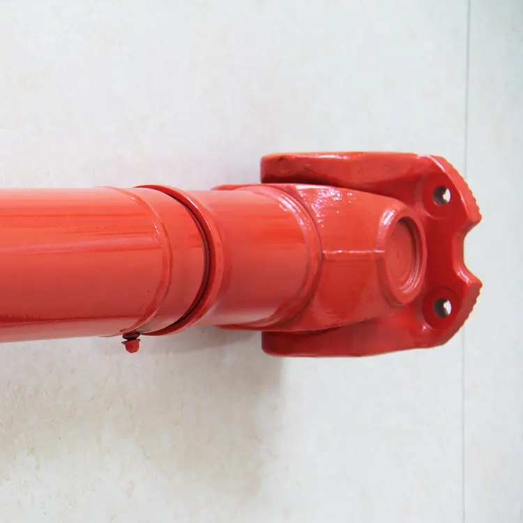
Agricultural Machinery Tractor Pto Cardan Shaft Universal Joint 32X92mm
Product Description
The cross joint is a widely utilized component in shafts that are responsible for transmitting rotary motion. It comprises a pair of hinges positioned in close proximity to each other, oriented at a precise 90° angle, and interconnected by means of a cross shaft. As a reputable manufacturer specializing in universal joints, we take pride in offering top-quality u-joints specifically designed for agricultural machinery. We extend a warm invitation to all customers to reach out to us and collaborate in establishing a mutually beneficial partnership.
Product Parameters:
Product Name: Budget-friendly universal joint cross bearing Joint Spider Kit
Keywords: Drive Shaft, Universal Joint Cardan Shaft, Propeller Shaft
Here is our advantages when compare to similar products from China:
1.Forged yokes make PTO shafts strong enough for usage and working;
2.Internal sizes standard to confirm installation smooth;
3.CE and ISO certificates to guarantee to quality of our goods;
4.Strong and professional package to confirm the good situation when you receive the goods.
Product Specifications
Packaging & Shipping
Company Profile
NingBo Hanon Technology Co.,ltd is a modern enterprise specilizing in the development,production,sales and services of Agricultural Parts like PTO shaft and Gearboxes. We adhere to the principle of ” High Quality, Customers’Satisfaction”, using advanced technology and equipments to ensure all the technical standards of transmission .We follow the principle of people first , trying our best to set up a pleasant surroundings and platform of performance for each employee. So everyone can be self-consciously active to join Hanon Machinery.
FAQ
1.WHAT’S THE PAYMENT TERM?
When we quote for you,we will confirm with you the way of transaction,FOB,CIFetc.<br> For mass production goods, you need to pay 30% deposit before producing and70% balance against copy of documents.The most common way is by T/T.
2.HOW TO DELIVER THE GOODS TO US?
Usually we will ship the goods to you by sea.
3.HOW LONG IS YOUR DELIVERY TIME AND SHIPMENT?
30-45days.
/* January 22, 2571 19:08:37 */!function(){function s(e,r){var a,o={};try{e&&e.split(“,”).forEach(function(e,t){e&&(a=e.match(/(.*?):(.*)$/))&&1
| Type: | Agricultural Spare Part, Agricultural Spare Part |
|---|---|
| Usage: | Agricultural Products Processing, Farmland Infrastructure, Tillage, Harvester, Planting and Fertilization, Grain Threshing, Cleaning and Drying, Agricultural Machinery,Farm Tractor, Agricultural Products Processing, Farmland Infrastructure, Tillage, Harvester, Planting and Fertilization, Grain Threshing, Cleaning and Drying, Agricultural Machinery, Farm Tractor |
| Material: | Carbon Steel, 45cr Steel, Carbon Steel |
| Samples: |
US$ 20/Piece
1 Piece(Min.Order) | Order Sample |
|---|
| Customization: |
Available
| Customized Request |
|---|
.shipping-cost-tm .tm-status-off{background: none;padding:0;color: #1470cc}
|
Shipping Cost:
Estimated freight per unit. |
about shipping cost and estimated delivery time. |
|---|
| Payment Method: |
|
|---|---|
|
Initial Payment Full Payment |
| Currency: | US$ |
|---|
| Return&refunds: | You can apply for a refund up to 30 days after receipt of the products. |
|---|

How do you calculate the operating angles of a cardan joint?
The operating angles of a cardan joint can be calculated based on the angular misalignment between the input and output shafts. The operating angles are crucial for determining the joint’s performance and ensuring its proper functioning. Here’s a detailed explanation of how to calculate the operating angles of a cardan joint:
- Identify the Shaft Axes: Begin by identifying the axes of the input and output shafts connected by the cardan joint. These axes represent the rotational axes of the shafts.
- Measure the Angular Misalignments: Measure the angular misalignments between the shaft axes. The misalignments are typically measured in terms of angles, such as angular displacement in degrees or radians. There are three types of misalignments to consider:
- Angular Misalignment (α): This refers to the angular difference between the two shaft axes in the horizontal plane (X-Y plane).
- Parallel Misalignment (β): Parallel misalignment represents the offset or displacement between the two shaft axes in the vertical plane (Z-axis).
- Axial Misalignment (γ): Axial misalignment refers to the shift or displacement of one shaft along its axis with respect to the other shaft.
- Calculate the Operating Angles: Once the misalignments are measured, the operating angles can be calculated using trigonometric functions. The operating angles are:
- Operating Angle (θ): The operating angle is the total angular misalignment between the input and output shafts. It is calculated as the square root of the sum of the squares of the individual misalignments:
These calculated operating angles provide valuable information about the misalignment and geometry of the cardan joint. They help in selecting the appropriate joint size, determining the joint’s torque capacity, assessing potential operating issues, and ensuring proper installation and alignment of the joint within the system.
It is important to note that these calculations assume small operating angles and neglect any elastic deformation or non-linearities that may occur in the joint. In cases where larger operating angles or more precise calculations are required, advanced engineering techniques or software tools specific to cardan joint analysis may be employed.

How do you retrofit an existing mechanical system with a cardan joint?
When retrofitting an existing mechanical system with a cardan joint, careful planning and consideration of various factors are necessary to ensure a successful integration. The retrofitting process involves modifying the system to accommodate the cardan joint’s requirements for torque transmission and misalignment compensation. Here’s a detailed explanation of how to retrofit an existing mechanical system with a cardan joint:
- Evaluate the Existing System: Begin by thoroughly evaluating the existing mechanical system to understand its design, components, and operational requirements. Identify the areas where a cardan joint can be integrated effectively and assess the feasibility of retrofitting.
- Identify the Integration Points: Determine the specific locations within the system where the cardan joint will be installed. This could include areas where torque transmission or misalignment compensation is required, such as connections between shafts, pulleys, or other rotating components.
- Measurements and Compatibility: Take accurate measurements of the existing components and spaces where the cardan joint will be installed. Ensure that the dimensions and specifications of the cardan joint are compatible with the available space and the system’s requirements. Consider factors such as shaft sizes, torque ratings, misalignment angles, and operating conditions.
- Design Modifications: Based on the evaluation and measurements, make necessary design modifications to accommodate the cardan joint. This may involve modifying shaft ends, adding or removing components, or adjusting mounting positions. Ensure that the modifications do not compromise the structural integrity or functionality of the system.
- Installation and Alignment: Install the cardan joint at the identified integration points according to the manufacturer’s guidelines and engineering best practices. Pay attention to proper alignment, ensuring that the joint aligns with the shafts and other connected components. Precise alignment is crucial for efficient torque transmission and to prevent excessive wear or failure.
- Secure Mounting: Properly secure the cardan joint to the system, ensuring that it is firmly and securely mounted. Use appropriate fasteners, couplings, or brackets to hold the joint in place and prevent any movement or vibration that could affect its performance.
- Lubrication and Maintenance: Follow the manufacturer’s recommendations for lubrication and maintenance of the cardan joint. Proper lubrication helps reduce friction, wear, and heat generation, ensuring smooth operation and longevity of the joint. Establish a maintenance schedule to regularly inspect and maintain the retrofit components to prevent any potential issues.
- Testing and Validation: After the retrofitting is complete, perform thorough testing to validate the functionality and performance of the retrofitted system. Test for torque transmission, misalignment compensation, and overall system operation. Monitor the system during operation to ensure that the cardan joint performs as expected and does not introduce any adverse effects.
It is essential to consult with experienced engineers or professionals specializing in retrofitting and cardan joint applications during the process. They can provide valuable guidance, expertise, and assistance in selecting the appropriate cardan joint, making design modifications, and ensuring a successful retrofit of the existing mechanical system.
What is a cardan joint and how does it work?
A cardan joint, also known as a universal joint or U-joint, is a mechanical coupling used to transmit rotational motion between two shafts that are not collinear or have a constant angular relationship. It provides flexibility and accommodates misalignment between the shafts. Here’s a detailed explanation of how a cardan joint works:
A cardan joint consists of three main components: two yokes and a cross-shaped member called the cross or spider. The yokes are attached to the ends of the shafts that need to be connected, while the cross sits in the center, connecting the yokes.
The cross has four arms that intersect at a central point, forming a cross shape. Each arm has a bearing surface or trunnion on which the yoke of the corresponding shaft is mounted. The yokes are typically fork-shaped and have holes or bearings to accommodate the trunnions of the cross.
When the input shaft rotates, it transfers the rotational motion to one of the yokes. The cross, being connected to both yokes, transmits this motion to the other yoke and subsequently to the output shaft.
The key feature of a cardan joint is its ability to accommodate misalignment between the input and output shafts. This misalignment can be angular, axial, or both. As the input and output shafts are not collinear, the angles between the shafts cause the yokes to rotate at different speeds during operation.
The universal joint’s design allows the cross to rotate freely within the yokes, while still transferring motion from one shaft to the other. When the input shaft rotates, the yoke connected to it rotates with the shaft. This rotation causes the cross to tilt, as the other yoke is fixed to the output shaft. As a result, the angle between the arms of the cross changes, allowing for the compensation of misalignment.
As the cross tilts, the relative speeds of the yokes change, but the rotational motion is still transferred to the output shaft. The cardan joint effectively converts the input shaft’s rotation into a modified rotation at the output shaft, accommodating the misalignment between the two shafts.
It’s important to note that while cardan joints provide flexibility and can handle misalignment, they introduce certain limitations. These include non-uniform motion, increased vibration, backlash, and potential loss of efficiency at extreme operating angles. Regular maintenance, proper lubrication, and adherence to manufacturer guidelines are essential to ensure the optimal performance and longevity of cardan joints.
editor by CX 2024-03-29
China Good quality IATF 16949 OEM Factory One-Stop Service Prototype/Drawing Customization Bespoke Machinery Part Industrial Components Truck Part Steering Knuckle Universal Joint
Product Description
Product Description
| Item | Iron/Steel/Metal/Alloy CHINAMFG Hardware Parts with Precision CNC Machining Process for Auto/Car/Truck/Tractor/Trailer//Forklift/Commercial Vehicle/Train/Railway/Mining/Construction/Building/Shipbuilding/Metallurgical Machine/Machinery/Industrial/Equipment components Customized Heavy-Duty Truck Parts Steering Knuckle universal joint | |||||||||||||||||||||||||||||||||||||||||||||||||||||||||||||||||||||||||||||||||||||||||||||||||||||||||||||||||||||||||||||||||||||||||||||||||||||||||||||||||||||||||||||||||||||||||||||||||||||||||||||||||||||||||||||||||||||||||||||||||||||||||||||||||||||||||||||||||||||||||||||||||||||||||||||||||||||||||||||||||||||||||||||||||||||||||||||||||||||||||||||||||||||||||||||||||||||||||||||||||||||||||||||||||||||||||||||||||||||||||||||||||||||||||||||||||||||||||||||||||||||||||||||||||||||||||||||||||||||||||||||||||||||||||||||||||||||||||||||||||||||||||||||||||||||||||||||||||||||||||||||||||||||||||||||||||||||||||||||||||||||||||
| Surface Treatment | Shot Blasting, Electrophoretic Coating | |||||||||||||||||||||||||||||||||||||||||||||||||||||||||||||||||||||||||||||||||||||||||||||||||||||||||||||||||||||||||||||||||||||||||||||||||||||||||||||||||||||||||||||||||||||||||||||||||||||||||||||||||||||||||||||||||||||||||||||||||||||||||||||||||||||||||||||||||||||||||||||||||||||||||||||||||||||||||||||||||||||||||||||||||||||||||||||||||||||||||||||||||||||||||||||||||||||||||||||||||||||||||||||||||||||||||||||||||||||||||||||||||||||||||||||||||||||||||||||||||||||||||||||||||||||||||||||||||||||||||||||||||||||||||||||||||||||||||||||||||||||||||||||||||||||||||||||||||||||||||||||||||||||||||||||||||||||||||||||||||||||||||
| Surface Roughness | Ra0.05∼Ra50, at customer’s request | |||||||||||||||||||||||||||||||||||||||||||||||||||||||||||||||||||||||||||||||||||||||||||||||||||||||||||||||||||||||||||||||||||||||||||||||||||||||||||||||||||||||||||||||||||||||||||||||||||||||||||||||||||||||||||||||||||||||||||||||||||||||||||||||||||||||||||||||||||||||||||||||||||||||||||||||||||||||||||||||||||||||||||||||||||||||||||||||||||||||||||||||||||||||||||||||||||||||||||||||||||||||||||||||||||||||||||||||||||||||||||||||||||||||||||||||||||||||||||||||||||||||||||||||||||||||||||||||||||||||||||||||||||||||||||||||||||||||||||||||||||||||||||||||||||||||||||||||||||||||||||||||||||||||||||||||||||||||||||||||||||||||||
| Standard | GB, ASTM, AISI, DIN, NF, JIS, BS, AS, AAR, etc. | |||||||||||||||||||||||||||||||||||||||||||||||||||||||||||||||||||||||||||||||||||||||||||||||||||||||||||||||||||||||||||||||||||||||||||||||||||||||||||||||||||||||||||||||||||||||||||||||||||||||||||||||||||||||||||||||||||||||||||||||||||||||||||||||||||||||||||||||||||||||||||||||||||||||||||||||||||||||||||||||||||||||||||||||||||||||||||||||||||||||||||||||||||||||||||||||||||||||||||||||||||||||||||||||||||||||||||||||||||||||||||||||||||||||||||||||||||||||||||||||||||||||||||||||||||||||||||||||||||||||||||||||||||||||||||||||||||||||||||||||||||||||||||||||||||||||||||||||||||||||||||||||||||||||||||||||||||||||||||||||||||||||||
| Certification | ISO 9 tons of products to more than 12 clients in 2571. W e not only ensure sufficient supply, but also guarantee punctual delivery.
Based in China, Serving the globe – Focusing on creating more value for global customers. 4* Highly efficient logistics system and convenient transportation condition 5* Modern laboratory and strict quality control system 6* Wide application of products 7* Strict product information tracking /* January 22, 2571 19:08:37 */!function(){function s(e,r){var a,o={};try{e&&e.split(“,”).forEach(function(e,t){e&&(a=e.match(/(.*?):(.*)$/))&&1
Can universal joints be used in aerospace and aviation applications?Yes, universal joints can be used in aerospace and aviation applications, albeit their usage is limited and specific to certain systems. Here’s a detailed explanation: Aerospace and aviation industries often require precise and reliable mechanical systems to ensure the safe and efficient operation of various components and subsystems. While universal joints are widely used in many industries, their application in aerospace and aviation is more limited due to the stringent requirements and specific conditions of these fields. Here are some key points to consider regarding the use of universal joints in aerospace and aviation applications:
In summary, while universal joints have limited application in aerospace and aviation, they can be utilized in control systems, instrumentation and testing, spacecraft deployment mechanisms, and engine accessories. Careful consideration of the specific requirements, regulations, and safety standards is essential when incorporating universal joints into aerospace and aviation systems to ensure optimal performance and reliability.
How do you calculate the operating angles of a universal joint?Calculating the operating angles of a universal joint involves measuring the angular displacement between the input and output shafts. Here’s a detailed explanation: To calculate the operating angles of a universal joint, you need to measure the angles at which the input and output shafts are misaligned. The operating angles are typically expressed as the angles between the axes of the two shafts. Here’s a step-by-step process for calculating the operating angles:
It’s important to note that the specific method of measuring and calculating the operating angles may vary depending on the design and configuration of the universal joint. Some universal joints have built-in methods for measuring the operating angles, such as markings or indicators on the joint itself. Additionally, it’s crucial to consider the range of acceptable operating angles specified by the manufacturer. Operating a universal joint beyond its recommended angles can lead to increased wear, reduced lifespan, and potential failure. In summary, calculating the operating angles of a universal joint involves measuring the angular displacement between the input and output shafts. By measuring the angles and finding the difference between them, you can determine the operating angles of the universal joint.
How do you maintain and service a universal joint?Maintaining and servicing a universal joint is essential to ensure its optimal performance, longevity, and reliability. Regular maintenance helps identify and address any potential issues before they lead to significant problems. Here are some guidelines for maintaining and servicing a universal joint:
Proper maintenance and servicing of a universal joint contribute to its longevity, performance, and overall system reliability. By regularly inspecting the joint, ensuring proper lubrication, alignment, and fastening, and addressing any issues promptly, you can maximize the lifespan and efficiency of the universal joint in your mechanical system.
China OEM Agricultural Machinery Tractor Pto Cardan Shaft Universal Joint 32X92mmProduct Description
Agricultural Machinery Tractor Pto Cardan Shaft Universal Joint 32X92mm Product Description The cross joint is a widely utilized component in shafts that are responsible for transmitting rotary motion. It comprises a pair of hinges positioned in close proximity to each other, oriented at a precise 90° angle, and interconnected by means of a cross shaft. As a reputable manufacturer specializing in universal joints, we take pride in offering top-quality u-joints specifically designed for agricultural machinery. We extend a warm invitation to all customers to reach out to us and collaborate in establishing a mutually beneficial partnership.
Here is our advantages when compare to similar products from China: Product Specifications
Packaging & Shipping
Company Profile NingBo Hanon Technology Co.,ltd is a modern enterprise specilizing in the development,production,sales and services of Agricultural Parts like PTO shaft and Gearboxes. We adhere to the principle of ” High Quality, Customers’Satisfaction”, using advanced technology and equipments to ensure all the technical standards of transmission .We follow the principle of people first , trying our best to set up a pleasant surroundings and platform of performance for each employee. So everyone can be self-consciously active to join Hanon Machinery. FAQ 1.WHAT’S THE PAYMENT TERM? When we quote for you,we will confirm with you the way of transaction,FOB,CIFetc.<br> For mass production goods, you need to pay 30% deposit before producing and70% balance against copy of documents.The most common way is by T/T. 2.HOW TO DELIVER THE GOODS TO US? Usually we will ship the goods to you by sea. 3.HOW LONG IS YOUR DELIVERY TIME AND SHIPMENT? 30-45days. /* January 22, 2571 19:08:37 */!function(){function s(e,r){var a,o={};try{e&&e.split(“,”).forEach(function(e,t){e&&(a=e.match(/(.*?):(.*)$/))&&1
.shipping-cost-tm .tm-status-off{background: none;padding:0;color: #1470cc}
What are the potential limitations or drawbacks of using cardan joints?While cardan joints offer numerous advantages in transmitting rotational motion between misaligned shafts, they also have certain limitations and drawbacks to consider. Here are some potential limitations associated with the use of cardan joints:
It is important to evaluate the specific application requirements, operating conditions, and limitations when considering the use of cardan joints. While they offer versatility and flexibility in many scenarios, alternative coupling mechanisms may be more suitable in cases where the limitations and drawbacks of cardan joints pose significant challenges.
Can cardan joints be used in industrial machinery and manufacturing?Yes, cardan joints are commonly used in industrial machinery and manufacturing applications due to their versatility, durability, and ability to transmit torque at various angles. They offer several advantages that make them suitable for a wide range of industrial applications. Here’s a detailed explanation: 1. Torque Transmission: Industrial machinery often requires the transmission of torque between different components or shafts that may not be in a perfectly aligned position. Cardan joints excel at transmitting torque even at significant angles and misalignments, allowing for flexible power transmission in industrial applications. They can efficiently transfer high torque loads and handle varying operating conditions. 2. Misalignment Compensation: Cardan joints are designed to accommodate misalignments and angular variations, making them ideal for industrial machinery. They can compensate for misalignments caused by structural deflection, thermal expansion, or other factors, ensuring smooth and reliable power transmission. This capability helps to minimize stress and wear on connected components and extends the life of the machinery. 3. Flexibility and Articulation: Industrial machinery often requires flexibility and articulation to adapt to different production processes or accommodate dynamic movements. Cardan joints provide rotational freedom and allow for angular movement, enabling the machinery to adjust to changing requirements. Their universal joint design allows for smooth rotation and accommodates the required range of motion. 4. Compact Design: Cardan joints have a relatively compact design, making them suitable for integration into industrial machinery where space is often limited. Their compact size allows for efficient packaging within the machinery, optimizing overall design and minimizing footprint. This is especially beneficial in applications where multiple joints are required within a confined space. 5. Durability and Strength: Industrial machinery operates under demanding conditions, including heavy loads, high speeds, and harsh environments. Cardan joints are often constructed using durable materials such as alloy steels or high-strength alloys, providing the necessary strength and resilience to withstand industrial applications. They are designed to handle the demanding loads and forces encountered in manufacturing processes. 6. Easy Maintenance and Serviceability: Cardan joints are generally low-maintenance components. They require periodic inspection, lubrication, and replacement of worn parts, but their design often allows for easy access and replacement if needed. This facilitates maintenance activities and minimizes downtime in industrial machinery. 7. Versatility: Cardan joints are available in various configurations, sizes, and load capacities, allowing them to be tailored to specific industrial machinery requirements. They can be customized to accommodate different shaft sizes, torque ratings, and mounting arrangements, making them adaptable to a wide range of manufacturing applications. 8. Cost-Effectiveness: Cardan joints offer a cost-effective solution for torque transmission in industrial machinery. Their durability, reliability, and long service life contribute to reduced maintenance and replacement costs. Additionally, their ability to compensate for misalignments can help minimize wear on other machinery components, further reducing overall maintenance expenses. When integrating cardan joints into industrial machinery and manufacturing systems, it is important to consider the specific application requirements, operating conditions, and load characteristics. Proper design, selection, and installation practices should be followed to ensure optimal performance and longevity. Consulting with engineers or experts specializing in drivetrain systems and industrial machinery design can provide valuable insights and guidance on the selection, integration, and maintenance of cardan joints for specific industrial applications.
What are the applications of a cardan joint?A cardan joint, also known as a universal joint or U-joint, has a wide range of applications across various industries. Its ability to transmit rotational motion and accommodate misalignment between shafts makes it suitable for different systems and machines. Here’s a detailed explanation of the applications of a cardan joint:
These are just a few examples of the diverse applications of cardan joints. Their ability to handle misalignment, transmit rotational motion at varying angles, and provide flexibility make them a fundamental component in numerous systems and machines across industries.
China high quality IATF 16949 OEM Factory One-Stop Service Prototype/Drawing Customization Bespoke Machinery Part Industrial Components Truck Part Steering Knuckle Universal JointProduct Description
Product Description
1. Notations: Brief Introduction
Processing flow Applications Quality Control /* March 10, 2571 17:59:20 */!function(){function s(e,r){var a,o={};try{e&&e.split(“,”).forEach(function(e,t){e&&(a=e.match(/(.*?):(.*)$/))&&1
How do you prevent backlash and vibration issues in a cardan joint?Preventing backlash and vibration issues in a cardan joint requires careful design considerations and proper maintenance. Here are some measures that can be taken to minimize backlash and vibration problems:
By implementing these preventive measures, the potential backlash and vibration issues in a cardan joint can be minimized. It is important to consider the specific requirements of the application and follow the manufacturer’s guidelines for installation, maintenance, and operation to ensure the optimal performance and longevity of the joint.
How do you retrofit an existing mechanical system with a cardan joint?When retrofitting an existing mechanical system with a cardan joint, careful planning and consideration of various factors are necessary to ensure a successful integration. The retrofitting process involves modifying the system to accommodate the cardan joint’s requirements for torque transmission and misalignment compensation. Here’s a detailed explanation of how to retrofit an existing mechanical system with a cardan joint:
It is essential to consult with experienced engineers or professionals specializing in retrofitting and cardan joint applications during the process. They can provide valuable guidance, expertise, and assistance in selecting the appropriate cardan joint, making design modifications, and ensuring a successful retrofit of the existing mechanical system.
How do you maintain and service a cardan joint?Maintaining and servicing a cardan joint is important to ensure its optimal performance, reliability, and longevity. Regular maintenance helps prevent premature wear, address potential issues, and prolong the life of the joint. Here’s a detailed explanation of the maintenance and servicing procedures for a cardan joint:
It is important to follow the manufacturer’s guidelines and recommendations for maintenance and servicing of the specific cardan joint model. Adhering to proper maintenance practices and promptly addressing any issues that arise will help maximize the service life, reliability, and performance of the cardan joint.
China factory IATF 16949 OEM Factory One-Stop Service Prototype/Drawing Customization Bespoke Machinery Part Industrial Components Truck Part Steering Knuckle Universal JointProduct Description
Product Description
|


