Product Description
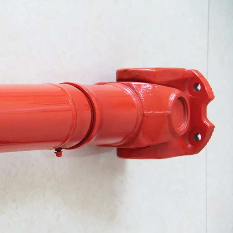
Agricultural Machinery Tractor Pto Cardan Shaft Universal Joint 32X92mm
Product Description
The cross joint is a widely utilized component in shafts that are responsible for transmitting rotary motion. It comprises a pair of hinges positioned in close proximity to each other, oriented at a precise 90° angle, and interconnected by means of a cross shaft. As a reputable manufacturer specializing in universal joints, we take pride in offering top-quality u-joints specifically designed for agricultural machinery. We extend a warm invitation to all customers to reach out to us and collaborate in establishing a mutually beneficial partnership.
Product Parameters:
Product Name: Budget-friendly universal joint cross bearing Joint Spider Kit
Keywords: Drive Shaft, Universal Joint Cardan Shaft, Propeller Shaft
Here is our advantages when compare to similar products from China:
1.Forged yokes make PTO shafts strong enough for usage and working;
2.Internal sizes standard to confirm installation smooth;
3.CE and ISO certificates to guarantee to quality of our goods;
4.Strong and professional package to confirm the good situation when you receive the goods.
Product Specifications
Packaging & Shipping
Company Profile
NingBo Hanon Technology Co.,ltd is a modern enterprise specilizing in the development,production,sales and services of Agricultural Parts like PTO shaft and Gearboxes. We adhere to the principle of ” High Quality, Customers’Satisfaction”, using advanced technology and equipments to ensure all the technical standards of transmission .We follow the principle of people first , trying our best to set up a pleasant surroundings and platform of performance for each employee. So everyone can be self-consciously active to join Hanon Machinery.
FAQ
1.WHAT’S THE PAYMENT TERM?
When we quote for you,we will confirm with you the way of transaction,FOB,CIFetc.<br> For mass production goods, you need to pay 30% deposit before producing and70% balance against copy of documents.The most common way is by T/T.
2.HOW TO DELIVER THE GOODS TO US?
Usually we will ship the goods to you by sea.
3.HOW LONG IS YOUR DELIVERY TIME AND SHIPMENT?
30-45days.
/* January 22, 2571 19:08:37 */!function(){function s(e,r){var a,o={};try{e&&e.split(“,”).forEach(function(e,t){e&&(a=e.match(/(.*?):(.*)$/))&&1
| Type: | Agricultural Spare Part, Agricultural Spare Part |
|---|---|
| Usage: | Agricultural Products Processing, Farmland Infrastructure, Tillage, Harvester, Planting and Fertilization, Grain Threshing, Cleaning and Drying, Agricultural Machinery,Farm Tractor, Agricultural Products Processing, Farmland Infrastructure, Tillage, Harvester, Planting and Fertilization, Grain Threshing, Cleaning and Drying, Agricultural Machinery, Farm Tractor |
| Material: | Carbon Steel, 45cr Steel, Carbon Steel |
| Samples: |
US$ 20/Piece
1 Piece(Min.Order) | Order Sample |
|---|
| Customization: |
Available
| Customized Request |
|---|
.shipping-cost-tm .tm-status-off{background: none;padding:0;color: #1470cc}
|
Shipping Cost:
Estimated freight per unit. |
about shipping cost and estimated delivery time. |
|---|
| Payment Method: |
|
|---|---|
|
Initial Payment Full Payment |
| Currency: | US$ |
|---|
| Return&refunds: | You can apply for a refund up to 30 days after receipt of the products. |
|---|

Are cardan joints suitable for both high-torque and high-speed applications?
Cardan joints can be used in a variety of applications, but their suitability for high-torque and high-speed applications depends on several factors. Here’s a detailed explanation of the considerations regarding the use of cardan joints in such scenarios:
1. High-Torque Applications: Cardan joints are generally well-suited for high-torque applications. The design of the joint allows for the transmission of significant torque between misaligned shafts. However, it is important to consider the specific torque requirements and operating conditions. Factors such as the size and type of the joint, the material used, and the application’s torque demands should be taken into account. In extremely high-torque applications, alternative coupling mechanisms such as gear couplings or universal joints may be more appropriate.
2. High-Speed Applications: While cardan joints can operate at relatively high speeds, there are some limitations to consider. At high rotational speeds, cardan joints can experience increased vibration, imbalance, and potential for fatigue failure. The rotating components of the joint can generate centrifugal forces, which can impact the balance and stability of the system. To mitigate these issues, careful design considerations, including balancing and vibration analysis, may be necessary. In some cases, alternative coupling mechanisms like flexible couplings or constant velocity joints may be better suited for high-speed applications.
3. Balancing and Vibration Control: Balancing the rotating components, such as the driveshaft and the joint itself, is essential for minimizing vibration issues in high-torque and high-speed applications. Imbalance can lead to increased vibrations, reduced efficiency, and potential damage to the joint and other system components. Proper balancing techniques, including dynamic balancing during manufacturing or precision balancing during installation, can help achieve smoother operation and minimize vibration problems.
4. Material Selection: The material used in the construction of the cardan joint plays a crucial role in its suitability for high-torque and high-speed applications. High-strength materials, such as alloy steels, are often preferred for their ability to handle increased torque loads. Additionally, materials with good fatigue resistance and high-speed capabilities can help ensure the durability and reliability of the joint in demanding applications.
5. Application-Specific Factors: The suitability of cardan joints for high-torque and high-speed applications also depends on the specific requirements and operating conditions of the application. Factors such as load characteristics, duty cycles, temperature, and environmental conditions should be considered. It is important to consult with the manufacturer or engineering experts to determine the appropriate size, type, and configuration of the cardan joint for a particular high-torque or high-speed application.
In summary, cardan joints can be suitable for both high-torque and high-speed applications, but careful consideration of factors such as torque requirements, speed limitations, balancing, material selection, and application-specific conditions is necessary. Evaluating these factors and consulting with experts can help determine the optimal coupling solution for a given high-torque or high-speed application.

How do you calculate the effect of misalignment on the life of a cardan joint?
Calculating the effect of misalignment on the life of a cardan joint involves considering various factors such as the magnitude of misalignment, operating conditions, and the specific design characteristics of the joint. While there is no universal formula for calculating the exact life reduction due to misalignment, certain guidelines and principles can help estimate the impact. Here’s a detailed explanation:
1. Misalignment Angle: Determine the misalignment angle between the input and output shafts connected by the cardan joint. The misalignment angle represents the angular deviation from the ideal alignment. It is typically measured in degrees or radians.
2. Operating Speed: Determine the operating speed of the cardan joint in rotations per minute (RPM) or radians per second. The operating speed affects the dynamic behavior and stresses experienced by the joint.
3. Load Conditions: Consider the load conditions under which the cardan joint operates. Factors such as the magnitude, direction, and variability of the applied loads can influence the joint’s fatigue life and susceptibility to misalignment-induced stress.
4. Joint Design and Specifications: Refer to the manufacturer’s documentation or design specifications for the cardan joint. Look for information related to the joint’s allowable misalignment limits, material properties, and fatigue characteristics. Manufacturers may provide guidelines or empirical data on the expected life reduction based on misalignment.
5. Empirical Models and Guidelines: Utilize empirical models or guidelines specific to cardan joints to estimate the life reduction caused by misalignment. These models are typically based on experimental data and observations. They may consider factors such as misalignment angle, operating speed, load conditions, and joint geometry to provide estimates of the life reduction percentage.
It’s important to note that the accuracy of the calculated life reduction due to misalignment depends on the assumptions made and the validity of the models or guidelines used. The actual life reduction may vary based on the specific operating conditions, joint design, material properties, and other factors not accounted for in the calculations.
Additionally, it is advisable to consult with the cardan joint manufacturer or industry experts who specialize in power transmission components. They can provide more accurate and detailed information regarding the expected life reduction due to misalignment for a specific cardan joint design and application.
Overall, while it is challenging to quantify the exact life reduction caused by misalignment in a cardan joint, considering the factors mentioned above and utilizing available guidelines can help estimate the potential impact and make informed decisions regarding joint selection, maintenance, and operating practices.
What are the benefits of using a cardan joint in a mechanical system?
A cardan joint, also known as a universal joint or U-joint, offers several benefits when used in a mechanical system. These benefits contribute to efficient power transmission, flexibility, and the ability to accommodate misalignment. Here’s a detailed explanation of the advantages of using a cardan joint:
- Misalignment Compensation: One of the primary advantages of a cardan joint is its ability to accommodate misalignment between the input and output shafts. The flexible design of the joint allows for angular misalignment, axial misalignment, or a combination of both. This capability is particularly useful in applications where the shafts are not perfectly aligned, or where movement and flexibility are required.
- Power Transmission: Cardan joints are efficient in transmitting rotational motion and torque between non-collinear shafts. They maintain a constant velocity ratio between the input and output shafts, ensuring smooth power transmission. This feature is especially beneficial in applications where a consistent and uninterrupted transfer of power is essential, such as drivetrain systems in vehicles and industrial machinery.
- Flexibility and Articulation: The flexible nature of a cardan joint allows for articulation and movement between the connected shafts. It enables the mechanical system to adapt to changing angles, positions, or misalignment during operation. This flexibility is particularly advantageous in applications that involve variable operating conditions, such as vehicles navigating uneven terrain or machinery with moving components.
- Torsional Vibration Damping: Cardan joints can help dampen torsional vibrations that may occur in a mechanical system. The cross-shaped design of the joint, combined with the flexibility of the bearings, can absorb and mitigate torsional vibrations, reducing stress on the components and improving overall system performance and durability.
- Compact Design: Cardan joints have a relatively compact design, allowing them to be easily integrated into various mechanical systems. They occupy less space compared to other types of power transmission components, making them suitable for applications with limited installation space or where weight reduction is a concern.
- Cost-Effectiveness: Cardan joints are generally cost-effective compared to alternative power transmission solutions. Their simple design, ease of manufacturing, and wide availability contribute to their affordability. Additionally, their durability and ability to handle misalignment can reduce the need for frequent maintenance or replacement, leading to cost savings in the long run.
These benefits make cardan joints a versatile and valuable component in numerous mechanical systems across industries such as automotive, industrial machinery, aerospace, marine, and more. Their ability to transmit power efficiently, accommodate misalignment, and provide flexibility contribute to improved performance, reliability, and operational efficiency of the overall mechanical system.


editor by CX 2024-04-16
China OEM Agricultural Machinery Tractor Pto Cardan Shaft Universal Joint 32X92mm
Product Description
Agricultural Machinery Tractor Pto Cardan Shaft Universal Joint 32X92mm
Product Description
The cross joint is a widely utilized component in shafts that are responsible for transmitting rotary motion. It comprises a pair of hinges positioned in close proximity to each other, oriented at a precise 90° angle, and interconnected by means of a cross shaft. As a reputable manufacturer specializing in universal joints, we take pride in offering top-quality u-joints specifically designed for agricultural machinery. We extend a warm invitation to all customers to reach out to us and collaborate in establishing a mutually beneficial partnership.
Product Parameters:
Product Name: Budget-friendly universal joint cross bearing Joint Spider Kit
Keywords: Drive Shaft, Universal Joint Cardan Shaft, Propeller Shaft
Here is our advantages when compare to similar products from China:
1.Forged yokes make PTO shafts strong enough for usage and working;
2.Internal sizes standard to confirm installation smooth;
3.CE and ISO certificates to guarantee to quality of our goods;
4.Strong and professional package to confirm the good situation when you receive the goods.
Product Specifications
Packaging & Shipping
Company Profile
NingBo Hanon Technology Co.,ltd is a modern enterprise specilizing in the development,production,sales and services of Agricultural Parts like PTO shaft and Gearboxes. We adhere to the principle of ” High Quality, Customers’Satisfaction”, using advanced technology and equipments to ensure all the technical standards of transmission .We follow the principle of people first , trying our best to set up a pleasant surroundings and platform of performance for each employee. So everyone can be self-consciously active to join Hanon Machinery.
FAQ
1.WHAT’S THE PAYMENT TERM?
When we quote for you,we will confirm with you the way of transaction,FOB,CIFetc.<br> For mass production goods, you need to pay 30% deposit before producing and70% balance against copy of documents.The most common way is by T/T.
2.HOW TO DELIVER THE GOODS TO US?
Usually we will ship the goods to you by sea.
3.HOW LONG IS YOUR DELIVERY TIME AND SHIPMENT?
30-45days.
/* January 22, 2571 19:08:37 */!function(){function s(e,r){var a,o={};try{e&&e.split(“,”).forEach(function(e,t){e&&(a=e.match(/(.*?):(.*)$/))&&1
| Type: | Agricultural Spare Part, Agricultural Spare Part |
|---|---|
| Usage: | Agricultural Products Processing, Farmland Infrastructure, Tillage, Harvester, Planting and Fertilization, Grain Threshing, Cleaning and Drying, Agricultural Machinery,Farm Tractor, Agricultural Products Processing, Farmland Infrastructure, Tillage, Harvester, Planting and Fertilization, Grain Threshing, Cleaning and Drying, Agricultural Machinery, Farm Tractor |
| Material: | Carbon Steel, 45cr Steel, Carbon Steel |
| Samples: |
US$ 20/Piece
1 Piece(Min.Order) | Order Sample |
|---|
| Customization: |
Available
| Customized Request |
|---|
.shipping-cost-tm .tm-status-off{background: none;padding:0;color: #1470cc}
|
Shipping Cost:
Estimated freight per unit. |
about shipping cost and estimated delivery time. |
|---|
| Payment Method: |
|
|---|---|
|
Initial Payment Full Payment |
| Currency: | US$ |
|---|
| Return&refunds: | You can apply for a refund up to 30 days after receipt of the products. |
|---|

How do you calculate the operating angles of a cardan joint?
The operating angles of a cardan joint can be calculated based on the angular misalignment between the input and output shafts. The operating angles are crucial for determining the joint’s performance and ensuring its proper functioning. Here’s a detailed explanation of how to calculate the operating angles of a cardan joint:
- Identify the Shaft Axes: Begin by identifying the axes of the input and output shafts connected by the cardan joint. These axes represent the rotational axes of the shafts.
- Measure the Angular Misalignments: Measure the angular misalignments between the shaft axes. The misalignments are typically measured in terms of angles, such as angular displacement in degrees or radians. There are three types of misalignments to consider:
- Angular Misalignment (α): This refers to the angular difference between the two shaft axes in the horizontal plane (X-Y plane).
- Parallel Misalignment (β): Parallel misalignment represents the offset or displacement between the two shaft axes in the vertical plane (Z-axis).
- Axial Misalignment (γ): Axial misalignment refers to the shift or displacement of one shaft along its axis with respect to the other shaft.
- Calculate the Operating Angles: Once the misalignments are measured, the operating angles can be calculated using trigonometric functions. The operating angles are:
- Operating Angle (θ): The operating angle is the total angular misalignment between the input and output shafts. It is calculated as the square root of the sum of the squares of the individual misalignments:
These calculated operating angles provide valuable information about the misalignment and geometry of the cardan joint. They help in selecting the appropriate joint size, determining the joint’s torque capacity, assessing potential operating issues, and ensuring proper installation and alignment of the joint within the system.
It is important to note that these calculations assume small operating angles and neglect any elastic deformation or non-linearities that may occur in the joint. In cases where larger operating angles or more precise calculations are required, advanced engineering techniques or software tools specific to cardan joint analysis may be employed.

How do you retrofit an existing mechanical system with a cardan joint?
When retrofitting an existing mechanical system with a cardan joint, careful planning and consideration of various factors are necessary to ensure a successful integration. The retrofitting process involves modifying the system to accommodate the cardan joint’s requirements for torque transmission and misalignment compensation. Here’s a detailed explanation of how to retrofit an existing mechanical system with a cardan joint:
- Evaluate the Existing System: Begin by thoroughly evaluating the existing mechanical system to understand its design, components, and operational requirements. Identify the areas where a cardan joint can be integrated effectively and assess the feasibility of retrofitting.
- Identify the Integration Points: Determine the specific locations within the system where the cardan joint will be installed. This could include areas where torque transmission or misalignment compensation is required, such as connections between shafts, pulleys, or other rotating components.
- Measurements and Compatibility: Take accurate measurements of the existing components and spaces where the cardan joint will be installed. Ensure that the dimensions and specifications of the cardan joint are compatible with the available space and the system’s requirements. Consider factors such as shaft sizes, torque ratings, misalignment angles, and operating conditions.
- Design Modifications: Based on the evaluation and measurements, make necessary design modifications to accommodate the cardan joint. This may involve modifying shaft ends, adding or removing components, or adjusting mounting positions. Ensure that the modifications do not compromise the structural integrity or functionality of the system.
- Installation and Alignment: Install the cardan joint at the identified integration points according to the manufacturer’s guidelines and engineering best practices. Pay attention to proper alignment, ensuring that the joint aligns with the shafts and other connected components. Precise alignment is crucial for efficient torque transmission and to prevent excessive wear or failure.
- Secure Mounting: Properly secure the cardan joint to the system, ensuring that it is firmly and securely mounted. Use appropriate fasteners, couplings, or brackets to hold the joint in place and prevent any movement or vibration that could affect its performance.
- Lubrication and Maintenance: Follow the manufacturer’s recommendations for lubrication and maintenance of the cardan joint. Proper lubrication helps reduce friction, wear, and heat generation, ensuring smooth operation and longevity of the joint. Establish a maintenance schedule to regularly inspect and maintain the retrofit components to prevent any potential issues.
- Testing and Validation: After the retrofitting is complete, perform thorough testing to validate the functionality and performance of the retrofitted system. Test for torque transmission, misalignment compensation, and overall system operation. Monitor the system during operation to ensure that the cardan joint performs as expected and does not introduce any adverse effects.
It is essential to consult with experienced engineers or professionals specializing in retrofitting and cardan joint applications during the process. They can provide valuable guidance, expertise, and assistance in selecting the appropriate cardan joint, making design modifications, and ensuring a successful retrofit of the existing mechanical system.
What is a cardan joint and how does it work?
A cardan joint, also known as a universal joint or U-joint, is a mechanical coupling used to transmit rotational motion between two shafts that are not collinear or have a constant angular relationship. It provides flexibility and accommodates misalignment between the shafts. Here’s a detailed explanation of how a cardan joint works:
A cardan joint consists of three main components: two yokes and a cross-shaped member called the cross or spider. The yokes are attached to the ends of the shafts that need to be connected, while the cross sits in the center, connecting the yokes.
The cross has four arms that intersect at a central point, forming a cross shape. Each arm has a bearing surface or trunnion on which the yoke of the corresponding shaft is mounted. The yokes are typically fork-shaped and have holes or bearings to accommodate the trunnions of the cross.
When the input shaft rotates, it transfers the rotational motion to one of the yokes. The cross, being connected to both yokes, transmits this motion to the other yoke and subsequently to the output shaft.
The key feature of a cardan joint is its ability to accommodate misalignment between the input and output shafts. This misalignment can be angular, axial, or both. As the input and output shafts are not collinear, the angles between the shafts cause the yokes to rotate at different speeds during operation.
The universal joint’s design allows the cross to rotate freely within the yokes, while still transferring motion from one shaft to the other. When the input shaft rotates, the yoke connected to it rotates with the shaft. This rotation causes the cross to tilt, as the other yoke is fixed to the output shaft. As a result, the angle between the arms of the cross changes, allowing for the compensation of misalignment.
As the cross tilts, the relative speeds of the yokes change, but the rotational motion is still transferred to the output shaft. The cardan joint effectively converts the input shaft’s rotation into a modified rotation at the output shaft, accommodating the misalignment between the two shafts.
It’s important to note that while cardan joints provide flexibility and can handle misalignment, they introduce certain limitations. These include non-uniform motion, increased vibration, backlash, and potential loss of efficiency at extreme operating angles. Regular maintenance, proper lubrication, and adherence to manufacturer guidelines are essential to ensure the optimal performance and longevity of cardan joints.
editor by CX 2024-03-29
China OEM Agricultural Machinery Tractor Pto Cardan Shaft Universal Joint 32X92mm
Product Description
Agricultural Machinery Tractor Pto Cardan Shaft Universal Joint 32X92mm
Product Description
The cross joint is a widely utilized component in shafts that are responsible for transmitting rotary motion. It comprises a pair of hinges positioned in close proximity to each other, oriented at a precise 90° angle, and interconnected by means of a cross shaft. As a reputable manufacturer specializing in universal joints, we take pride in offering top-quality u-joints specifically designed for agricultural machinery. We extend a warm invitation to all customers to reach out to us and collaborate in establishing a mutually beneficial partnership.
Product Parameters:
Product Name: Budget-friendly universal joint cross bearing Joint Spider Kit
Keywords: Drive Shaft, Universal Joint Cardan Shaft, Propeller Shaft
Here is our advantages when compare to similar products from China:
1.Forged yokes make PTO shafts strong enough for usage and working;
2.Internal sizes standard to confirm installation smooth;
3.CE and ISO certificates to guarantee to quality of our goods;
4.Strong and professional package to confirm the good situation when you receive the goods.
Product Specifications
Packaging & Shipping
Company Profile
NingBo Hanon Technology Co.,ltd is a modern enterprise specilizing in the development,production,sales and services of Agricultural Parts like PTO shaft and Gearboxes. We adhere to the principle of ” High Quality, Customers’Satisfaction”, using advanced technology and equipments to ensure all the technical standards of transmission .We follow the principle of people first , trying our best to set up a pleasant surroundings and platform of performance for each employee. So everyone can be self-consciously active to join Hanon Machinery.
FAQ
1.WHAT’S THE PAYMENT TERM?
When we quote for you,we will confirm with you the way of transaction,FOB,CIFetc.<br> For mass production goods, you need to pay 30% deposit before producing and70% balance against copy of documents.The most common way is by T/T.
2.HOW TO DELIVER THE GOODS TO US?
Usually we will ship the goods to you by sea.
3.HOW LONG IS YOUR DELIVERY TIME AND SHIPMENT?
30-45days.
/* January 22, 2571 19:08:37 */!function(){function s(e,r){var a,o={};try{e&&e.split(“,”).forEach(function(e,t){e&&(a=e.match(/(.*?):(.*)$/))&&1
| Type: | Agricultural Spare Part, Agricultural Spare Part |
|---|---|
| Usage: | Agricultural Products Processing, Farmland Infrastructure, Tillage, Harvester, Planting and Fertilization, Grain Threshing, Cleaning and Drying, Agricultural Machinery,Farm Tractor, Agricultural Products Processing, Farmland Infrastructure, Tillage, Harvester, Planting and Fertilization, Grain Threshing, Cleaning and Drying, Agricultural Machinery, Farm Tractor |
| Material: | Carbon Steel, 45cr Steel, Carbon Steel |
| Samples: |
US$ 20/Piece
1 Piece(Min.Order) | Order Sample |
|---|
| Customization: |
Available
| Customized Request |
|---|
.shipping-cost-tm .tm-status-off{background: none;padding:0;color: #1470cc}
|
Shipping Cost:
Estimated freight per unit. |
about shipping cost and estimated delivery time. |
|---|
| Payment Method: |
|
|---|---|
|
Initial Payment Full Payment |
| Currency: | US$ |
|---|
| Return&refunds: | You can apply for a refund up to 30 days after receipt of the products. |
|---|
What are the potential limitations or drawbacks of using cardan joints?
While cardan joints offer numerous advantages in transmitting rotational motion between misaligned shafts, they also have certain limitations and drawbacks to consider. Here are some potential limitations associated with the use of cardan joints:
- Angular Limitations: Cardan joints have limited angularity or operating angles. They are designed to operate within specific angular ranges, and exceeding these angles can cause accelerated wear, increased vibration, and potential joint failure. Extreme operating angles can lead to binding, decreased efficiency, and reduced power transmission capacity. In applications where large operating angles are required, alternative flexible coupling mechanisms or constant velocity joints may be more suitable.
- Backlash and Torsional Stiffness: Cardan joints inherently exhibit some degree of backlash, which is the clearance or free play between the mating components. This can result in a slight delay in power transmission and can affect the precision of motion in certain applications. Additionally, cardan joints may have higher torsional stiffness compared to other coupling mechanisms, which can transmit higher vibrations and shocks to the connected components.
- Maintenance Requirements: Cardan joints require regular maintenance to ensure proper lubrication, alignment, and performance. The lubricant needs to be regularly replenished or replaced, and the joint should be inspected for wear, misalignment, or other issues. Failure to perform adequate maintenance can result in premature wear, reduced efficiency, and potential joint failure. Maintenance procedures may require specialized tools and expertise.
- Space and Weight: Cardan joints can occupy a significant amount of space due to their design and the need for perpendicular shafts. In applications with limited space constraints, finding suitable locations for cardan joints can be challenging. Additionally, the weight of cardan joints, especially in heavy-duty applications, can add to the overall weight of the system, which may have implications for fuel efficiency, payload capacity, or overall performance.
- Cost: Cardan joints, particularly high-quality and precision-engineered ones, can be relatively expensive compared to other coupling mechanisms. The complex design, manufacturing tolerances, and specialized materials involved contribute to their higher cost. In cost-sensitive applications, alternative coupling solutions may be considered if the angular limitations and other drawbacks of cardan joints are not critical.
- High-Speed Limitations: At high rotational speeds, cardan joints can experience increased vibration, imbalance, and potential for fatigue failure. The rotating components of the joint can generate centrifugal forces that impact the balance and stability of the system. In high-speed applications, careful design considerations, including balancing and vibration analysis, may be necessary to mitigate these issues.
It is important to evaluate the specific application requirements, operating conditions, and limitations when considering the use of cardan joints. While they offer versatility and flexibility in many scenarios, alternative coupling mechanisms may be more suitable in cases where the limitations and drawbacks of cardan joints pose significant challenges.
Can cardan joints be used in industrial machinery and manufacturing?
Yes, cardan joints are commonly used in industrial machinery and manufacturing applications due to their versatility, durability, and ability to transmit torque at various angles. They offer several advantages that make them suitable for a wide range of industrial applications. Here’s a detailed explanation:
1. Torque Transmission: Industrial machinery often requires the transmission of torque between different components or shafts that may not be in a perfectly aligned position. Cardan joints excel at transmitting torque even at significant angles and misalignments, allowing for flexible power transmission in industrial applications. They can efficiently transfer high torque loads and handle varying operating conditions.
2. Misalignment Compensation: Cardan joints are designed to accommodate misalignments and angular variations, making them ideal for industrial machinery. They can compensate for misalignments caused by structural deflection, thermal expansion, or other factors, ensuring smooth and reliable power transmission. This capability helps to minimize stress and wear on connected components and extends the life of the machinery.
3. Flexibility and Articulation: Industrial machinery often requires flexibility and articulation to adapt to different production processes or accommodate dynamic movements. Cardan joints provide rotational freedom and allow for angular movement, enabling the machinery to adjust to changing requirements. Their universal joint design allows for smooth rotation and accommodates the required range of motion.
4. Compact Design: Cardan joints have a relatively compact design, making them suitable for integration into industrial machinery where space is often limited. Their compact size allows for efficient packaging within the machinery, optimizing overall design and minimizing footprint. This is especially beneficial in applications where multiple joints are required within a confined space.
5. Durability and Strength: Industrial machinery operates under demanding conditions, including heavy loads, high speeds, and harsh environments. Cardan joints are often constructed using durable materials such as alloy steels or high-strength alloys, providing the necessary strength and resilience to withstand industrial applications. They are designed to handle the demanding loads and forces encountered in manufacturing processes.
6. Easy Maintenance and Serviceability: Cardan joints are generally low-maintenance components. They require periodic inspection, lubrication, and replacement of worn parts, but their design often allows for easy access and replacement if needed. This facilitates maintenance activities and minimizes downtime in industrial machinery.
7. Versatility: Cardan joints are available in various configurations, sizes, and load capacities, allowing them to be tailored to specific industrial machinery requirements. They can be customized to accommodate different shaft sizes, torque ratings, and mounting arrangements, making them adaptable to a wide range of manufacturing applications.
8. Cost-Effectiveness: Cardan joints offer a cost-effective solution for torque transmission in industrial machinery. Their durability, reliability, and long service life contribute to reduced maintenance and replacement costs. Additionally, their ability to compensate for misalignments can help minimize wear on other machinery components, further reducing overall maintenance expenses.
When integrating cardan joints into industrial machinery and manufacturing systems, it is important to consider the specific application requirements, operating conditions, and load characteristics. Proper design, selection, and installation practices should be followed to ensure optimal performance and longevity.
Consulting with engineers or experts specializing in drivetrain systems and industrial machinery design can provide valuable insights and guidance on the selection, integration, and maintenance of cardan joints for specific industrial applications.
What are the applications of a cardan joint?
A cardan joint, also known as a universal joint or U-joint, has a wide range of applications across various industries. Its ability to transmit rotational motion and accommodate misalignment between shafts makes it suitable for different systems and machines. Here’s a detailed explanation of the applications of a cardan joint:
- Automotive Drivetrains: One of the primary applications of cardan joints is in automotive drivetrains. They are used in vehicles with rear-wheel drive, all-wheel drive, and four-wheel drive systems. Cardan joints help transmit power from the engine to the driveshaft, allowing the rotational motion to be transferred to the rear axle or all four wheels. They provide flexibility and compensation for misalignment between the engine, transmission, and rear differential.
- Industrial Machinery: Cardan joints find extensive use in various industrial machinery applications. They are commonly employed in power transmission systems, especially when there is a need to transmit rotational motion between non-collinear shafts. Cardan joints are used in conveyor systems, printing presses, machine tools, pumps, mixers, and many other industrial machines that require efficient transmission of rotational power.
- Aerospace and Aviation: Cardan joints have applications in the aerospace and aviation industries. They are used in aircraft control systems, such as the control linkages between the control surfaces (elevator, rudder, ailerons) and the cockpit controls. Cardan joints allow for the transmission of pilot input to the control surfaces while accommodating any misalignment or changes in angles during flight.
- Marine Propulsion: In marine applications, cardan joints are utilized in propulsion systems. They are commonly used in boat drivetrains to transfer rotational motion from the engine to the propeller shaft. Cardan joints enable the engine to be mounted at an angle or in a different position from the propeller shaft, compensating for the misalignment that can arise due to the boat’s hull shape and design.
- Railway Systems: Cardan joints play a role in railway systems, particularly in drivetrains and couplings. They are used in locomotives and train cars to transfer rotational motion between different components, such as the engine, gearbox, and wheel axle. Cardan joints provide flexibility and accommodate misalignment that may occur due to the movement and articulation of train cars on curved tracks.
- Mining and Construction Equipment: Cardan joints are employed in heavy-duty mining and construction equipment. They are used in applications such as excavators, loaders, bulldozers, and off-highway trucks. Cardan joints help transmit power and motion between different components of these machines, allowing them to operate efficiently and withstand the demanding conditions of mining and construction environments.
- Industrial Robotics: Cardan joints find applications in industrial robotics and automation. They are used in robotic arms and manipulators to transmit rotational motion between different segments or joints of the robotic system. Cardan joints enable precise and flexible movement, allowing robots to perform complex tasks in manufacturing, assembly, and other industrial processes.
These are just a few examples of the diverse applications of cardan joints. Their ability to handle misalignment, transmit rotational motion at varying angles, and provide flexibility make them a fundamental component in numerous systems and machines across industries.
editor by CX 2024-03-10
China Best Sales Tractor Part Friction Torque Limiter / Pto Drive Cardan Shaft /Propeller Shaft for Agriculture Machinery CE Certificate with Free Design Custom
Product Description
Tractor Part Friction Torque Limiter / Pto Drive Cardan Shaft /Propeller Shaft for Agriculture Machinery Ce Certificate
Power Take Off Shafts for all applications
A power take-off or power takeoff (PTO) is any of several methods for taking power from a power source, such as a running engine, and transmitting it to an application such as an attached implement or separate machines.
Most commonly, it is a splined drive shaft installed on a tractor or truck allowing implements with mating fittings to be powered directly by the engine.
Semi-permanently mounted power take-offs can also be found on industrial and marine engines. These applications typically use a drive shaft and bolted joint to transmit power to a secondary implement or accessory. In the case of a marine application, such shafts may be used to power fire pumps.
We offer high-quality PTO shaft parts and accessories, including clutches, tubes, and yokes for your tractor and implements, including an extensive range of pto driveline. Request our pto shaft products at the best rate possible.
What does a power take off do?
Power take-off (PTO) is a device that transfers an engine’s mechanical power to another piece of equipment. A PTO allows the hosting energy source to transmit power to additional equipment that does not have its own engine or motor. For example, a PTO helps to run a jackhammer using a tractor engine.
What’s the difference between 540 and 1000 PTO?
When a PTO shaft is turning 540, the ratio must be adjusted (geared up or down) to meet the needs of the implement, which is usually higher RPM’s than that. Since 1000 RPM’s is almost double that of 540, there is less “”Gearing Up”” designed in the implement to do the job required.”
If you are looking for a PTO speed reducer visit here
| Function | Power transmission |
| Use | Tractors and various farm implements |
| Place of Origin | HangZhou ,ZHangZhoug, China (Mainland) |
| Brand Name | EPT |
| Yoke Type | push pin/quick release/collar/double push pin/bolt pins/split pins |
| Processing Of Yoke | Forging |
| Plastic Cover | YW;BW;YS;BS |
| Color | Yellow;black |
| Series | T series; L series; S series |
| Tube Type | Trianglar/star/lemon |
| Processing Of Tube | Cold drawn |
| Spline Type | 1 3/8″ Z6; 1 3/8 Z21 ;1 3/4 Z20;1 1/8 Z6; 1 3/4 Z6; |
Related Products
Application:
Company information:
Axle Spindle Types and Features
The axle spindle is an integral part of your vehicle’s suspension. There are several different types and features, including mounting methods, bearings, and functions. Read on for some basic information on axle spindles. The next part of the article will cover how to choose the correct axle spindle for your vehicle. This article will also discuss the different types of spindles available, including the differences between the rear and front bearings.
Features
The improved axle spindle nut assembly is capable of providing additional performance benefits, including increased tire life and reduced seal failure. Its keyway features and radially inwardly extending teeth allow nut adjustment to be accomplished with precision. The invention further provides a unique, multi-piece locking mechanism that minimizes leakage and torque transfer. Its principles and features are detailed in the appended claims. For example, the improved axle spindle nut assembly is designed for use in vehicles that are equipped with a steering system.
The axle spindle nut assembly includes a nut 252 with threads 256 on its inner periphery. The axle spindle 50 also features threads 198 on its outer periphery. The nut is threaded onto the outboard end of the axle spindle 50 until it contacts the inboard surface of the axle spacer 26. In the assembled state, a bearing spacer 58 is also present on the axle spindle.
The axle spindle nut assembly can reduce axial end play between the wheel end assembly 52 and the axle spindle 50. It can be tightened to an extreme torque level, but if the thread faces separate, it will undercompress the bearing cone and spacer group. To minimize these disadvantages, the axle spindle nut assembly is a critical component of a wheel-end assembly. There are several types of axle spindle nuts.
The third embodiment of the axle spindle nut assembly 300 comprises an inner washer 202, an outer washer 310, and at least 1 screw 320. The axle spindle nut assembly 300 secures and preloads bearing cones 55, 57. Unlike the first embodiment, the axle spindle nut assembly 300 uses the inner washer 202, which is optional in the third embodiment. The inner washer 202 and outer washer 310 are similar to those of the first embodiment.
Functions
An axle spindle is 1 of the most important components of a vehicle’s suspension system. The spindle retains the position of bearings and a spacer in an axle by providing clamp force. The inner nut of an axle spindle should be properly torqued to ensure a secure fit. A spindle nut is also responsible for compressing bearings and spacers. If any of these components are missing, the spindle will not work properly.
An axle spindle is used in rear wheel drive cars. It carries the weight of the vehicle on the axle casing and transfers the torque from the differential to the wheels. The axle spindle and hub are secured on the spindle by large nuts. The axle spindle is a vital component of rear wheel drive vehicles. Hence, it is essential to understand the functions of axle spindle. These components are responsible for the smooth operation of a vehicle’s suspension system.
Axle spindles can be mounted in 3 ways: in the typical axle assembly, the spindles are bolted onto the ends of the tubular axle, and the axle is suspended by springs. Short stub-axle mounting uses a torsion beam that flexes to provide a smooth ride. A second washer is used to prevent excessive rotation of the axle spindle.
Apart from being a crucial component of the suspension system, the spindles of the wheels are responsible for guiding the vehicle in a straight line. They are connected to the steering axis and are used in different types of suspension systems. European cars use a MacPherson Strut suspension system in which the spindle is connected to the arms in the front and rear of the suspension frame. The MacPherson strut allows the shock absorber housing to turn the wheel.
Methods of mounting
Various methods of mounting axle spindle are available. In general, these methods involve forming a tubular blank of uniform cross section and thickness, and receiving the bearing assembly against it. The spindle is then secured using a collar, which also serves as a bearing stop. In some cases, additional features are used to provide greater security. Some of these features may not be suitable for all applications. But they are generally suitable.
Axle spindle forming is usually done by progressive steps using hollow punches. The metallic body of the punch has an inner work surface, which receives the axle blank. A mandrel is fixed within the work opening of the punch. The punch body’s work surface forges the spindle about the mandrel. The punch has 2 ends, a closed and an open one.
A wheeled vehicle axle assembly (10) includes a cylindrical housing member (12 a) and a plurality of spindle mounting flanges (30) secured on the housing member. The spindles (16) are firmly attached to the housing member by means of coupling members. The coupling members are configured to distribute the bending loads imposed on the spindle by the axle. It is important to note that the coupling members can be either threaded or screwed.
Traditionally, axle spindles were made from tubular blanks of irregular thickness. This method allowed for a gradual reduction in diameter and eliminated the need for extra metal within the spindle. Similarly, axles made by cold forming eliminate the need for additional metal in the spindle. In this way, the overall cost of manufacture is also reduced. The material used for manufacturing axles also determines the size and shape of the final product.
Bearings
A nut 16 is used to retain the wheel bearings on axle spindle 12. The nut comprises several parts. The first portion includes a plurality of threads and a deformable second portion. The nut may be disposed on the inboard or outboard end of the axle spindle. This type of nut is typically secured to the axle spindle by a retaining nut.
The bearings are installed in the spindle to allow the wheel hub to rotate. While bearings are greased, they can dry out over time. Consequently, you may hear a loud clicking sound when turning your vehicle. Alternatively, you may notice grease on the edges of your tires. Bearing failure can cause severe damage to your axle spindle. If you notice any of these symptoms, you may need to replace the bearings on your axle spindle. Fortunately, you can purchase the necessary bearing parts at O’Reilly Auto Parts.
There are 3 ways to mount an axle spindle. A typical axle assembly has the spindles bolted to the ends of the tubular axle. A torsion beam is also used to mount the spindles on the axle. This torsion beam acts like a spring to help make the ride smooth and bump-free. Lastly, the axle spindle is sometimes mounted as a bolt-on component.
Cost
If your axle spindle has been damaged, you may need to have it replaced. This part of the axle is relatively easy to replace, but you need to know how to do it correctly. To replace your axle spindle, you must first remove the damaged one. To do this, a technician will cut the weld. They will then thread the new 1 into the axle tube and torque it to specification. After that, they will weld the new axle spindle into place.
When you are thinking about the cost of an axle spindle replacement, you must first determine if it is worth it for your vehicle. It is generally a good idea to replace the spindle only if it is causing damage to your vehicle. You can also replace your axle housing if it is deteriorating. If you do not replace the spindle, you can risk damaging the axle housing. To save money, you can consider using a repair kit.
You can also purchase an axle nut socket set. Most wrenches have an adjusting socket for this purpose. The socket set should be suitable for most vehicle types. Axle spindle replacement costs around $500 to $600 before tax. However, you should be aware that these costs vary widely based on the type of vehicle you have. The parts can cost between $430 and $480, and the labor can cost anywhere from $50 to 70.


China manufacturer Agriculture Machinery Parts Cardan Transmission Tractor Parts Pto Drive Shaft Practical Drive Shaft with CE Certificate OEM ODM with Best Sales
Product Description
Agriculture Machinery parts Cardan Transmission Tractor Parts Pto Drive Shaft Practical Drive Shaft with CE Certificate OEM ODM
Power Take Off Shafts for all applications
A power take-off or power takeoff (PTO) is any of several methods for taking power from a power source, such as a running engine, and transmitting it to an application such as an attached implement or separate machines.
Most commonly, it is a splined drive shaft installed on a tractor or truck allowing implements with mating fittings to be powered directly by the engine.
Semi-permanently mounted power take-offs can also be found on industrial and marine engines. These applications typically use a drive shaft and bolted joint to transmit power to a secondary implement or accessory. In the case of a marine application, such shafts may be used to power fire pumps.
We offer high-quality PTO shaft parts and accessories, including clutches, tubes, and yokes for your tractor and implements, including an extensive range of pto driveline. Request our pto shaft products at the best rate possible.
What does a power take off do?
Power take-off (PTO) is a device that transfers an engine’s mechanical power to another piece of equipment. A PTO allows the hosting energy source to transmit power to additional equipment that does not have its own engine or motor. For example, a PTO helps to run a jackhammer using a tractor engine.
What’s the difference between 540 and 1000 PTO?
When a PTO shaft is turning 540, the ratio must be adjusted (geared up or down) to meet the needs of the implement, which is usually higher RPM’s than that. Since 1000 RPM’s is almost double that of 540, there is less “”Gearing Up”” designed in the implement to do the job required.”
If you are looking for a PTO speed reducer visit here
| Function | Power transmission |
| Use | Tractors and various farm implements |
| Place of Origin | HangZhou ,ZHangZhoug, China (Mainland) |
| Brand Name | EPT |
| Yoke Type | push pin/quick release/collar/double push pin/bolt pins/split pins |
| Processing Of Yoke | Forging |
| Plastic Cover | YW;BW;YS;BS |
| Color | Yellow;black |
| Series | T series; L series; S series |
| Tube Type | Trianglar/star/lemon |
| Processing Of Tube | Cold drawn |
| Spline Type | 1 3/8″ Z6; 1 3/8 Z21 ;1 3/4 Z20;1 1/8 Z6; 1 3/4 Z6; |
Related Products
Application:
Company information:
Worm Gear Motors
Worm gear motors are often preferred for quieter operation because of the smooth sliding motion of the worm shaft. Unlike gear motors with teeth, which may click as the worm turns, worm gear motors can be installed in a quiet area. In this article, we will talk about the CZPT whirling process and the various types of worms available. We’ll also discuss the benefits of worm gear motors and worm wheel.
worm gear
In the case of a worm gear, the axial pitch of the ring pinion of the corresponding revolving worm is equal to the circular pitch of the mating revolving pinion of the worm gear. A worm with 1 start is known as a worm with a lead. This leads to a smaller worm wheel. Worms can work in tight spaces because of their small profile.
Generally, a worm gear has high efficiency, but there are a few disadvantages. Worm gears are not recommended for high-heat applications because of their high level of rubbing. A full-fluid lubricant film and the low wear level of the gear reduce friction and wear. Worm gears also have a lower wear rate than a standard gear. The worm shaft and worm gear is also more efficient than a standard gear.
The worm gear shaft is cradled within a self-aligning bearing block that is attached to the gearbox casing. The eccentric housing has radial bearings on both ends, enabling it to engage with the worm gear wheel. The drive is transferred to the worm gear shaft through bevel gears 13A, 1 fixed at the ends of the worm gear shaft and the other in the center of the cross-shaft.
worm wheel
In a worm gearbox, the pinion or worm gear is centered between a geared cylinder and a worm shaft. The worm gear shaft is supported at either end by a radial thrust bearing. A gearbox’s cross-shaft is fixed to a suitable drive means and pivotally attached to the worm wheel. The input drive is transferred to the worm gear shaft 10 through bevel gears 13A, 1 of which is fixed to the end of the worm gear shaft and the other at the centre of the cross-shaft.
Worms and worm wheels are available in several materials. The worm wheel is made of bronze alloy, aluminum, or steel. Aluminum bronze worm wheels are a good choice for high-speed applications. Cast iron worm wheels are cheap and suitable for light loads. MC nylon worm wheels are highly wear-resistant and machinable. Aluminum bronze worm wheels are available and are good for applications with severe wear conditions.
When designing a worm wheel, it is vital to determine the correct lubricant for the worm shaft and a corresponding worm wheel. A suitable lubricant should have a kinematic viscosity of 300 mm2/s and be used for worm wheel sleeve bearings. The worm wheel and worm shaft should be properly lubricated to ensure their longevity.
Multi-start worms
A multi-start worm gear screw jack combines the benefits of multiple starts with linear output speeds. The multi-start worm shaft reduces the effects of single start worms and large ratio gears. Both types of worm gears have a reversible worm that can be reversed or stopped by hand, depending on the application. The worm gear’s self-locking ability depends on the lead angle, pressure angle, and friction coefficient.
A single-start worm has a single thread running the length of its shaft. The worm advances 1 tooth per revolution. A multi-start worm has multiple threads in each of its threads. The gear reduction on a multi-start worm is equal to the number of teeth on the gear minus the number of starts on the worm shaft. In general, a multi-start worm has 2 or 3 threads.
Worm gears can be quieter than other types of gears because the worm shaft glides rather than clicking. This makes them an excellent choice for applications where noise is a concern. Worm gears can be made of softer material, making them more noise-tolerant. In addition, they can withstand shock loads. Compared to gears with toothed teeth, worm gears have a lower noise and vibration rate.
CZPT whirling process
The CZPT whirling process for worm shafts raises the bar for precision gear machining in small to medium production volumes. The CZPT whirling process reduces thread rolling, increases worm quality, and offers reduced cycle times. The CZPT LWN-90 whirling machine features a steel bed, programmable force tailstock, and five-axis interpolation for increased accuracy and quality.
Its 4,000-rpm, 5-kW whirling spindle produces worms and various types of screws. Its outer diameters are up to 2.5 inches, while its length is up to 20 inches. Its dry-cutting process uses a vortex tube to deliver chilled compressed air to the cutting point. Oil is also added to the mixture. The worm shafts produced are free of undercuts, reducing the amount of machining required.
Induction hardening is a process that takes advantage of the whirling process. The induction hardening process utilizes alternating current (AC) to cause eddy currents in metallic objects. The higher the frequency, the higher the surface temperature. The electrical frequency is monitored through sensors to prevent overheating. Induction heating is programmable so that only certain parts of the worm shaft will harden.
Common tangent at an arbitrary point on both surfaces of the worm wheel
A worm gear consists of 2 helical segments with a helix angle equal to 90 degrees. This shape allows the worm to rotate with more than 1 tooth per rotation. A worm’s helix angle is usually close to 90 degrees and the body length is fairly long in the axial direction. A worm gear with a lead angle g has similar properties as a screw gear with a helix angle of 90 degrees.
The axial cross section of a worm gear is not conventionally trapezoidal. Instead, the linear part of the oblique side is replaced by cycloid curves. These curves have a common tangent near the pitch line. The worm wheel is then formed by gear cutting, resulting in a gear with 2 meshing surfaces. This worm gear can rotate at high speeds and still operate quietly.
A worm wheel with a cycloid pitch is a more efficient worm gear. It reduces friction between the worm and the gear, resulting in greater durability, improved operating efficiency, and reduced noise. This pitch line also helps the worm wheel engage more evenly and smoothly. Moreover, it prevents interference with their appearance. It also makes worm wheel and gear engagement smoother.
Calculation of worm shaft deflection
There are several methods for calculating worm shaft deflection, and each method has its own set of disadvantages. These commonly used methods provide good approximations but are inadequate for determining the actual worm shaft deflection. For example, these methods do not account for the geometric modifications to the worm, such as its helical winding of teeth. Furthermore, they overestimate the stiffening effect of the gearing. Hence, efficient thin worm shaft designs require other approaches.
Fortunately, several methods exist to determine the maximum worm shaft deflection. These methods use the finite element method, and include boundary conditions and parameter calculations. Here, we look at a couple of methods. The first method, DIN 3996, calculates the maximum worm shaft deflection based on the test results, while the second one, AGMA 6022, uses the root diameter of the worm as the equivalent bending diameter.
The second method focuses on the basic parameters of worm gearing. We’ll take a closer look at each. We’ll examine worm gearing teeth and the geometric factors that influence them. Commonly, the range of worm gearing teeth is 1 to four, but it can be as large as twelve. Choosing the teeth should depend on optimization requirements, including efficiency and weight. For example, if a worm gearing needs to be smaller than the previous model, then a small number of teeth will suffice.