Tag Archives: tractor sales

China 3.5 Tons Wheel Loader Drive Axle 100-140 HP Tractor Driving Axle with Caliper Brake with Best Sales

Merchandise Description

Product Description

  • Two-phase decelerating construction is adopted for push axle.
  • Spiral bevel gears with great bearing capability and high efficiency are adopted for primary push.
  • The wheel is planetary decelerating framework.
  • The principal reducer is outfitted with the widespread bevel-gear differential mechanism with easy framework and adaptable differential function.
  • Cast metal with adequate rigidity serves as substance for the axle housing.
  • The brake in clamp-disc braking manner has fantastic braking second.
  • Appropriate for 3.5 tons wheel loader and one hundred-a hundred and forty horsepower tractor.

Product Parameters


Main Link Proportions

Product L1 L2 L3 A B C D H h flange Rotation direction(front)
QWL35 875 1825 2146 one hundred and five 155 336 M20×1.5 150 seventy five Spherical flange Ananti clockwise
QWL35(1) 875 1825 2146 105 one hundred fifty five 336 M20×1.five a hundred and fifty seventy five Spherical flange Clockwise
QWL35(2) 865 1825 2146 95 160 330 M20×1.5 a hundred seventy five one hundred Sq. Flange Clockwise
QWL35(3) 865 1825 2146 95 a hundred and sixty 330 M22×1.5 190 a hundred Square Flange Ananti clockwise
QWL35(4) 865 1825 2146 ninety five 160 330 M22×1.five 190 90 Square Flange Ananti clockwise
QWL35(5) 865 1825 2146 95 a hundred and sixty 330 M22×1.5 one hundred eighty ninety Sq. Flange Ananti clockwise
QWL35(6) 960 1825 2146 a hundred/140 one hundred sixty 336 M22×1.five 180 ninety Square Flange Ananti clockwise

Specialized Parameters
Main transmission ratio Transmission ratio at wheel Whole transmission ratio Axle load Enter torque Clamp-disc sort brake
Cylinder variety Cylinder diameter Braking oil stress Oil inlet Brake radius Brake moment
five.286 three.88 twenty.52 19000kg 2800N.m four Ф75 nine.8MPa M12×1.25 186mm 9660N.m/personal computer

Our Rewards

Company Profile

HangZhou Tsingleader Sector Co., Ltd. is found in the stunning HangZhou metropolis. We specialize in the generation of trailer areas, axle and transmission of engineering equipment and unique engineering and agricultural equipment.
Over the earlier many years, Tsingleader Sector has invested 4 manufacturing vegetation in China. Following the theory of “good quality assurance, abiding by the agreement, reciprocity, mutual reward and first-class solutions”, we have gained the have confidence in from our clientele each at residence and abroad.
Our yearly product sales quantity reaches USD 5 million and our products have been exported to North and South The united states, Europe ,Africa,South Asia and the Middle East.
We sincerely hope to turn out to be your earnest business companion and your make contact with will be warmly welcomed.


US $1,000-7,000
/ Piece
|
1 Piece

(Min. Order)

###

After-sales Service: All Lifecircle
Warranty: 1 Year
Type: Axle
Application: Wheel Loader
Certification: CE, ISO9001: 2000
Condition: New

###

Samples:
US$ 1000/Piece
1 Piece(Min.Order)

|
Request Sample

###

Customization:

###

Model L1 L2 L3 A B C D H h flange Rotation direction(front)
QWL35 875 1825 2146 105 155 336 M20×1.5 150 75 Round flange Ananti clockwise
QWL35(1) 875 1825 2146 105 155 336 M20×1.5 150 75 Round flange Clockwise
QWL35(2) 865 1825 2146 95 160 330 M20×1.5 175 100 Square Flange Clockwise
QWL35(3) 865 1825 2146 95 160 330 M22×1.5 190 100 Square Flange Ananti clockwise
QWL35(4) 865 1825 2146 95 160 330 M22×1.5 190 90 Square Flange Ananti clockwise
QWL35(5) 865 1825 2146 95 160 330 M22×1.5 180 90 Square Flange Ananti clockwise
QWL35(6) 960 1825 2146 100/140 160 336 M22×1.5 180 90 Square Flange Ananti clockwise

###

Main transmission ratio Transmission ratio at wheel Total transmission ratio Axle load Input torque Clamp-disc type brake
Cylinder number Cylinder diameter Braking oil pressure Oil inlet Brake radius Brake moment
5.286 3.88 20.52 19000kg 2800N.m 4 Ф75 9.8MPa M12×1.25 186mm 9660N.m/pc

Different Types of Axles

An axle is the central shaft of a gear or wheel. It can be mounted to a wheel or to the vehicle itself, and will rotate with the wheels and vehicle. It may also contain bearings. Some vehicles have different types of axles, including Live, Split, Tandem, and Drop-out axles.

Live axle

A beam axle, also called a rigid axle, is a type of dependent suspension system. It connects a set of wheels lateral to one another. In previous times, beam axles were used in the rear of a vehicle, and later on, as the front axle in four-wheel-drive vehicles.
Live axles are also popular on trucks. They can provide better traction and keep the vehicle at a constant height. This is especially helpful for off-road vehicles. Those vehicles are typically driven slowly and the suspension is not as important as handling and cornering. Nonetheless, some trucks still use this design. It can be a great option if you are looking for a vehicle that handles well.
Live axles have a number of drawbacks. The front end of a live axle can destabilize and affect cornering grip. They also require a means of locating the axle, which may be an issue with heavy or lightweight vehicles. Leaf springs can help in this regard. Alternatively, you can opt for an independent rear axle.
Live axles are a great option for drag racing vehicles. They offer better traction and a better structural base than a conventional full floater axle assembly. They also allow for increased gear life and reduce rear end distortion.
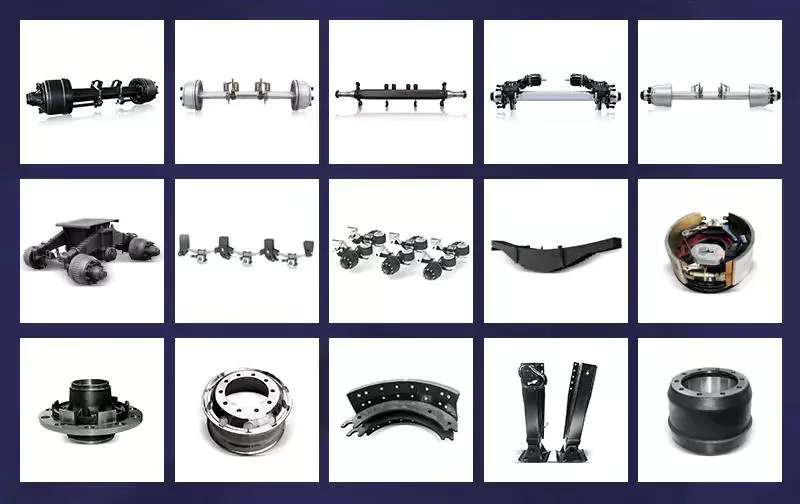
Axles

Split-axle

If you aren’t sure how to make split axles, you’re not alone. The process can be very difficult, and the parts can get mixed up. The key is to know how to create the proper alignment for your axles. Thankfully, there are some tools that can make this job a breeze.
Split axles have two components: a bolt head 30 that acts as a stop during relative pivotal movement. The axle assembly 16 is then pivotally mounted between the brackets and the frame. During pivotal movement, the bolt head 30 acts as a stop and prevents the axle from moving too far either way. This is done to maintain the pad 28 at a predetermined compression level. This allows the axle to perform a smooth and consistent drive.
Split axles are a common feature of modern vehicles. This type of suspension system provides greater traction, and it allows the left and right wheels to roll at different speeds. It also prolongs the life of tires, and increases traction.

Tandem

A tandem axle trailer is a great choice for hauling large loads. This style of trailer comes with more features and is more stable. These trailers are usually available in 16′, 18′, or 20′ lengths. They are also available with 8,500, or 10,000 GVW capacities. They are a great choice for hauling large loads on main highways.
Tandem axles are commonly used on trucks. Each axle features a drive mechanism, and are attached to the engine power unit. There are two types of tandem axles, one with a standard differential and the other with a power divider. Drivers may have trouble figuring out which axle is driving the truck at different times, so it is important to understand how each type of axle works.
While there are some common rules that apply to tandem axles, there are also some exceptions. In some cases, a single axle has a lower weight limit than a tandem axle, and the two axles must be at least 40 inches apart.

Drop-out

Drop-out axles are used to connect the dropouts of a bike frame. When using dropouts, make sure the distance between the axles is 110mm. Then use a clamp to squeeze the dropouts together. Make sure to measure both dropouts carefully, because a 1mm difference in the width can cause a lot of trouble.
The 9″ drop-out axle was produced from the late 1950s to 1986. They were made in trucks and cars, but not in motorcycles. To use this axle in a 1990 LTD CV, you will need to make several modifications to the mounting of the axle and connection to the drive line. You will also need to consider installing a parking brake. Moreover, this axle is not compatible with the Panther platform. In fact, the drop-out axle is available in several variations.
Drop-out axles are also known as single-speed. The lower part is called the semi-horizontal dropout, while the upper part is called the vertical dropout. This dropout includes an eyelet for mounting a fender or rack.
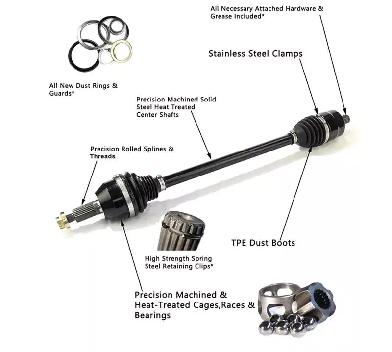
Axles

Czpt

The Czpt axle is a popular choice for a wide variety of vehicles. Initially used in heavy-duty pickup trucks, it was eventually adopted by all major automakers in the U.S., including Ford, Dodge, and Chrysler. It also became popular as a front differential on 4WD vehicles.
Czpt axles are easy to recognize, and the numbering system is consistent regardless of the vehicle model. The axle’s model number is found on the right lower web of the housing near the pinion yoke. It is also stamped on the axle tube. If you can’t find the axle model number, you can find it on Czpt’s website.
Czpt axles are also recognizable by their Bill of Materials (BOM) number. This is like a vehicle’s VIN number, and it identifies the axle’s gear ratio, model number, and component parts. A Czpt axle’s BOM number starts with 60 or 61.
The Czpt axle is the most common axle size in Jeeps. The Czpt 30 axle is the standard, and can be found on most Jeeps. The YJ version of this axle uses a reverse cut ring and pinion, while the TJ version does not. It is made from 5×4.5 inch bolts.

Universal joint

A universal joint is a component that connects two wheels to one another. This component is made to replace worn out or damaged parts on axles. They are also used to repair and replace brakes and drive shaft yokes. The universal joint can be purchased at an auto parts store or online. To replace a universal joint, you need to remove the axle shaft and the front brakes.
The universal joint is a flexible pivot point that transfers power between two shafts. In order to work properly, it must be flexible enough to compensate for changes in the driveline angle. These changes may be due to changing terrain. The universal joint is an important part of the driveline. It is used in both manual and automatic transmissions.
A universal joint should be serviced regularly to maintain its performance. If your universal joint squeaks while driving, it is a sign that it needs to be serviced. A lubricant can help extend the life of a u-joint.
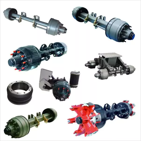
Axles

Spindle

Your vehicle’s axle consists of two main components: the hub and the spindle. The spindle rides on the hub, which can become damaged or lose its shape when it hits something. The spindle is also prone to wear from high mileage, and its threads can be damaged. If you suspect that your spindle needs to be replaced, there are several options available.
Axle spindles can be installed in one of three ways. The typical assembly includes bolted spindles on the ends of a tubular axle. The axle is then suspended by springs. Another type of mounting involves a torsion beam on the axle leg, which acts as a spring. It flexes and bends to provide the turning motion. The axle spindle can be a replacement part for your trailer, and there are towing supplies and professionals who can do it for you.
China 3.5 Tons Wheel Loader Drive Axle 100-140 HP Tractor Driving Axle with Caliper Brake     with Best Sales China 3.5 Tons Wheel Loader Drive Axle 100-140 HP Tractor Driving Axle with Caliper Brake     with Best Sales
editor by czh 2022-12-17

China Best Sales Tractor Part Friction Torque Limiter / Pto Drive Cardan Shaft /Propeller Shaft for Agriculture Machinery CE Certificate with Free Design Custom

Product Description

Tractor Part Friction Torque Limiter / Pto Drive Cardan Shaft /Propeller Shaft for Agriculture Machinery Ce Certificate

Power Take Off Shafts for all applications

A power take-off or power takeoff (PTO) is any of several methods for taking power from a power source, such as a running engine, and transmitting it to an application such as an attached implement or separate machines.

Most commonly, it is a splined drive shaft installed on a tractor or truck allowing implements with mating fittings to be powered directly by the engine.

Semi-permanently mounted power take-offs can also be found on industrial and marine engines. These applications typically use a drive shaft and bolted joint to transmit power to a secondary implement or accessory. In the case of a marine application, such shafts may be used to power fire pumps.

We offer high-quality PTO shaft parts and accessories, including clutches, tubes, and yokes for your tractor and implements, including an extensive range of pto driveline. Request our pto shaft products at the best rate possible.

What does a power take off do?

Power take-off (PTO) is a device that transfers an engine’s mechanical power to another piece of equipment. A PTO allows the hosting energy source to transmit power to additional equipment that does not have its own engine or motor. For example, a PTO helps to run a jackhammer using a tractor engine.

What’s the difference between 540 and 1000 PTO?

When a PTO shaft is turning 540, the ratio must be adjusted (geared up or down) to meet the needs of the implement, which is usually higher RPM’s than that. Since 1000 RPM’s is almost double that of 540, there is less “”Gearing Up”” designed in the implement to do the job required.”

If you are looking for a PTO speed reducer visit here 

Function Power transmission                                   
Use Tractors and various farm implements
Place of Origin HangZhou ,ZHangZhoug, China (Mainland)
Brand Name EPT
Yoke Type push pin/quick release/collar/double push pin/bolt pins/split pins 
Processing Of Yoke Forging
Plastic Cover YW;BW;YS;BS
Color Yellow;black
Series T series; L series; S series
Tube Type Trianglar/star/lemon
Processing Of Tube Cold drawn
Spline Type 1 3/8″ Z6; 1 3/8 Z21 ;1 3/4 Z20;1 1/8 Z6; 1 3/4 Z6; 

Related Products

Application:

Company information:


Axle Spindle Types and Features

The axle spindle is an integral part of your vehicle’s suspension. There are several different types and features, including mounting methods, bearings, and functions. Read on for some basic information on axle spindles. The next part of the article will cover how to choose the correct axle spindle for your vehicle. This article will also discuss the different types of spindles available, including the differences between the rear and front bearings.
Driveshaft

Features

The improved axle spindle nut assembly is capable of providing additional performance benefits, including increased tire life and reduced seal failure. Its keyway features and radially inwardly extending teeth allow nut adjustment to be accomplished with precision. The invention further provides a unique, multi-piece locking mechanism that minimizes leakage and torque transfer. Its principles and features are detailed in the appended claims. For example, the improved axle spindle nut assembly is designed for use in vehicles that are equipped with a steering system.
The axle spindle nut assembly includes a nut 252 with threads 256 on its inner periphery. The axle spindle 50 also features threads 198 on its outer periphery. The nut is threaded onto the outboard end of the axle spindle 50 until it contacts the inboard surface of the axle spacer 26. In the assembled state, a bearing spacer 58 is also present on the axle spindle.
The axle spindle nut assembly can reduce axial end play between the wheel end assembly 52 and the axle spindle 50. It can be tightened to an extreme torque level, but if the thread faces separate, it will undercompress the bearing cone and spacer group. To minimize these disadvantages, the axle spindle nut assembly is a critical component of a wheel-end assembly. There are several types of axle spindle nuts.
The third embodiment of the axle spindle nut assembly 300 comprises an inner washer 202, an outer washer 310, and at least 1 screw 320. The axle spindle nut assembly 300 secures and preloads bearing cones 55, 57. Unlike the first embodiment, the axle spindle nut assembly 300 uses the inner washer 202, which is optional in the third embodiment. The inner washer 202 and outer washer 310 are similar to those of the first embodiment.

Functions

An axle spindle is 1 of the most important components of a vehicle’s suspension system. The spindle retains the position of bearings and a spacer in an axle by providing clamp force. The inner nut of an axle spindle should be properly torqued to ensure a secure fit. A spindle nut is also responsible for compressing bearings and spacers. If any of these components are missing, the spindle will not work properly.
An axle spindle is used in rear wheel drive cars. It carries the weight of the vehicle on the axle casing and transfers the torque from the differential to the wheels. The axle spindle and hub are secured on the spindle by large nuts. The axle spindle is a vital component of rear wheel drive vehicles. Hence, it is essential to understand the functions of axle spindle. These components are responsible for the smooth operation of a vehicle’s suspension system.
Axle spindles can be mounted in 3 ways: in the typical axle assembly, the spindles are bolted onto the ends of the tubular axle, and the axle is suspended by springs. Short stub-axle mounting uses a torsion beam that flexes to provide a smooth ride. A second washer is used to prevent excessive rotation of the axle spindle.
Apart from being a crucial component of the suspension system, the spindles of the wheels are responsible for guiding the vehicle in a straight line. They are connected to the steering axis and are used in different types of suspension systems. European cars use a MacPherson Strut suspension system in which the spindle is connected to the arms in the front and rear of the suspension frame. The MacPherson strut allows the shock absorber housing to turn the wheel.
Driveshaft

Methods of mounting

Various methods of mounting axle spindle are available. In general, these methods involve forming a tubular blank of uniform cross section and thickness, and receiving the bearing assembly against it. The spindle is then secured using a collar, which also serves as a bearing stop. In some cases, additional features are used to provide greater security. Some of these features may not be suitable for all applications. But they are generally suitable.
Axle spindle forming is usually done by progressive steps using hollow punches. The metallic body of the punch has an inner work surface, which receives the axle blank. A mandrel is fixed within the work opening of the punch. The punch body’s work surface forges the spindle about the mandrel. The punch has 2 ends, a closed and an open one.
A wheeled vehicle axle assembly (10) includes a cylindrical housing member (12 a) and a plurality of spindle mounting flanges (30) secured on the housing member. The spindles (16) are firmly attached to the housing member by means of coupling members. The coupling members are configured to distribute the bending loads imposed on the spindle by the axle. It is important to note that the coupling members can be either threaded or screwed.
Traditionally, axle spindles were made from tubular blanks of irregular thickness. This method allowed for a gradual reduction in diameter and eliminated the need for extra metal within the spindle. Similarly, axles made by cold forming eliminate the need for additional metal in the spindle. In this way, the overall cost of manufacture is also reduced. The material used for manufacturing axles also determines the size and shape of the final product.
Driveshaft

Bearings

A nut 16 is used to retain the wheel bearings on axle spindle 12. The nut comprises several parts. The first portion includes a plurality of threads and a deformable second portion. The nut may be disposed on the inboard or outboard end of the axle spindle. This type of nut is typically secured to the axle spindle by a retaining nut.
The bearings are installed in the spindle to allow the wheel hub to rotate. While bearings are greased, they can dry out over time. Consequently, you may hear a loud clicking sound when turning your vehicle. Alternatively, you may notice grease on the edges of your tires. Bearing failure can cause severe damage to your axle spindle. If you notice any of these symptoms, you may need to replace the bearings on your axle spindle. Fortunately, you can purchase the necessary bearing parts at O’Reilly Auto Parts.
There are 3 ways to mount an axle spindle. A typical axle assembly has the spindles bolted to the ends of the tubular axle. A torsion beam is also used to mount the spindles on the axle. This torsion beam acts like a spring to help make the ride smooth and bump-free. Lastly, the axle spindle is sometimes mounted as a bolt-on component.

Cost

If your axle spindle has been damaged, you may need to have it replaced. This part of the axle is relatively easy to replace, but you need to know how to do it correctly. To replace your axle spindle, you must first remove the damaged one. To do this, a technician will cut the weld. They will then thread the new 1 into the axle tube and torque it to specification. After that, they will weld the new axle spindle into place.
When you are thinking about the cost of an axle spindle replacement, you must first determine if it is worth it for your vehicle. It is generally a good idea to replace the spindle only if it is causing damage to your vehicle. You can also replace your axle housing if it is deteriorating. If you do not replace the spindle, you can risk damaging the axle housing. To save money, you can consider using a repair kit.
You can also purchase an axle nut socket set. Most wrenches have an adjusting socket for this purpose. The socket set should be suitable for most vehicle types. Axle spindle replacement costs around $500 to $600 before tax. However, you should be aware that these costs vary widely based on the type of vehicle you have. The parts can cost between $430 and $480, and the labor can cost anywhere from $50 to 70.

China Best Sales Tractor Part Friction Torque Limiter / Pto Drive Cardan Shaft /Propeller Shaft for Agriculture Machinery CE Certificate   with Free Design CustomChina Best Sales Tractor Part Friction Torque Limiter / Pto Drive Cardan Shaft /Propeller Shaft for Agriculture Machinery CE Certificate   with Free Design Custom

China manufacturer Agriculture Machinery Parts Cardan Transmission Tractor Parts Pto Drive Shaft Practical Drive Shaft with CE Certificate OEM ODM with Best Sales

Product Description

Agriculture Machinery parts Cardan Transmission Tractor Parts Pto Drive Shaft Practical Drive Shaft with CE Certificate OEM ODM

Power Take Off Shafts for all applications

A power take-off or power takeoff (PTO) is any of several methods for taking power from a power source, such as a running engine, and transmitting it to an application such as an attached implement or separate machines.

Most commonly, it is a splined drive shaft installed on a tractor or truck allowing implements with mating fittings to be powered directly by the engine.

Semi-permanently mounted power take-offs can also be found on industrial and marine engines. These applications typically use a drive shaft and bolted joint to transmit power to a secondary implement or accessory. In the case of a marine application, such shafts may be used to power fire pumps.

We offer high-quality PTO shaft parts and accessories, including clutches, tubes, and yokes for your tractor and implements, including an extensive range of pto driveline. Request our pto shaft products at the best rate possible.

What does a power take off do?

Power take-off (PTO) is a device that transfers an engine’s mechanical power to another piece of equipment. A PTO allows the hosting energy source to transmit power to additional equipment that does not have its own engine or motor. For example, a PTO helps to run a jackhammer using a tractor engine.

What’s the difference between 540 and 1000 PTO?

When a PTO shaft is turning 540, the ratio must be adjusted (geared up or down) to meet the needs of the implement, which is usually higher RPM’s than that. Since 1000 RPM’s is almost double that of 540, there is less “”Gearing Up”” designed in the implement to do the job required.”

If you are looking for a PTO speed reducer visit here 

Function Power transmission                                   
Use Tractors and various farm implements
Place of Origin HangZhou ,ZHangZhoug, China (Mainland)
Brand Name EPT
Yoke Type push pin/quick release/collar/double push pin/bolt pins/split pins 
Processing Of Yoke Forging
Plastic Cover YW;BW;YS;BS
Color Yellow;black
Series T series; L series; S series
Tube Type Trianglar/star/lemon
Processing Of Tube Cold drawn
Spline Type 1 3/8″ Z6; 1 3/8 Z21 ;1 3/4 Z20;1 1/8 Z6; 1 3/4 Z6; 

Related Products

Application:

Company information:


Worm Gear Motors

Worm gear motors are often preferred for quieter operation because of the smooth sliding motion of the worm shaft. Unlike gear motors with teeth, which may click as the worm turns, worm gear motors can be installed in a quiet area. In this article, we will talk about the CZPT whirling process and the various types of worms available. We’ll also discuss the benefits of worm gear motors and worm wheel.
worm shaft

worm gear

In the case of a worm gear, the axial pitch of the ring pinion of the corresponding revolving worm is equal to the circular pitch of the mating revolving pinion of the worm gear. A worm with 1 start is known as a worm with a lead. This leads to a smaller worm wheel. Worms can work in tight spaces because of their small profile.
Generally, a worm gear has high efficiency, but there are a few disadvantages. Worm gears are not recommended for high-heat applications because of their high level of rubbing. A full-fluid lubricant film and the low wear level of the gear reduce friction and wear. Worm gears also have a lower wear rate than a standard gear. The worm shaft and worm gear is also more efficient than a standard gear.
The worm gear shaft is cradled within a self-aligning bearing block that is attached to the gearbox casing. The eccentric housing has radial bearings on both ends, enabling it to engage with the worm gear wheel. The drive is transferred to the worm gear shaft through bevel gears 13A, 1 fixed at the ends of the worm gear shaft and the other in the center of the cross-shaft.

worm wheel

In a worm gearbox, the pinion or worm gear is centered between a geared cylinder and a worm shaft. The worm gear shaft is supported at either end by a radial thrust bearing. A gearbox’s cross-shaft is fixed to a suitable drive means and pivotally attached to the worm wheel. The input drive is transferred to the worm gear shaft 10 through bevel gears 13A, 1 of which is fixed to the end of the worm gear shaft and the other at the centre of the cross-shaft.
Worms and worm wheels are available in several materials. The worm wheel is made of bronze alloy, aluminum, or steel. Aluminum bronze worm wheels are a good choice for high-speed applications. Cast iron worm wheels are cheap and suitable for light loads. MC nylon worm wheels are highly wear-resistant and machinable. Aluminum bronze worm wheels are available and are good for applications with severe wear conditions.
When designing a worm wheel, it is vital to determine the correct lubricant for the worm shaft and a corresponding worm wheel. A suitable lubricant should have a kinematic viscosity of 300 mm2/s and be used for worm wheel sleeve bearings. The worm wheel and worm shaft should be properly lubricated to ensure their longevity.

Multi-start worms

A multi-start worm gear screw jack combines the benefits of multiple starts with linear output speeds. The multi-start worm shaft reduces the effects of single start worms and large ratio gears. Both types of worm gears have a reversible worm that can be reversed or stopped by hand, depending on the application. The worm gear’s self-locking ability depends on the lead angle, pressure angle, and friction coefficient.
A single-start worm has a single thread running the length of its shaft. The worm advances 1 tooth per revolution. A multi-start worm has multiple threads in each of its threads. The gear reduction on a multi-start worm is equal to the number of teeth on the gear minus the number of starts on the worm shaft. In general, a multi-start worm has 2 or 3 threads.
Worm gears can be quieter than other types of gears because the worm shaft glides rather than clicking. This makes them an excellent choice for applications where noise is a concern. Worm gears can be made of softer material, making them more noise-tolerant. In addition, they can withstand shock loads. Compared to gears with toothed teeth, worm gears have a lower noise and vibration rate.
worm shaft

CZPT whirling process

The CZPT whirling process for worm shafts raises the bar for precision gear machining in small to medium production volumes. The CZPT whirling process reduces thread rolling, increases worm quality, and offers reduced cycle times. The CZPT LWN-90 whirling machine features a steel bed, programmable force tailstock, and five-axis interpolation for increased accuracy and quality.
Its 4,000-rpm, 5-kW whirling spindle produces worms and various types of screws. Its outer diameters are up to 2.5 inches, while its length is up to 20 inches. Its dry-cutting process uses a vortex tube to deliver chilled compressed air to the cutting point. Oil is also added to the mixture. The worm shafts produced are free of undercuts, reducing the amount of machining required.
Induction hardening is a process that takes advantage of the whirling process. The induction hardening process utilizes alternating current (AC) to cause eddy currents in metallic objects. The higher the frequency, the higher the surface temperature. The electrical frequency is monitored through sensors to prevent overheating. Induction heating is programmable so that only certain parts of the worm shaft will harden.

Common tangent at an arbitrary point on both surfaces of the worm wheel

A worm gear consists of 2 helical segments with a helix angle equal to 90 degrees. This shape allows the worm to rotate with more than 1 tooth per rotation. A worm’s helix angle is usually close to 90 degrees and the body length is fairly long in the axial direction. A worm gear with a lead angle g has similar properties as a screw gear with a helix angle of 90 degrees.
The axial cross section of a worm gear is not conventionally trapezoidal. Instead, the linear part of the oblique side is replaced by cycloid curves. These curves have a common tangent near the pitch line. The worm wheel is then formed by gear cutting, resulting in a gear with 2 meshing surfaces. This worm gear can rotate at high speeds and still operate quietly.
A worm wheel with a cycloid pitch is a more efficient worm gear. It reduces friction between the worm and the gear, resulting in greater durability, improved operating efficiency, and reduced noise. This pitch line also helps the worm wheel engage more evenly and smoothly. Moreover, it prevents interference with their appearance. It also makes worm wheel and gear engagement smoother.
worm shaft

Calculation of worm shaft deflection

There are several methods for calculating worm shaft deflection, and each method has its own set of disadvantages. These commonly used methods provide good approximations but are inadequate for determining the actual worm shaft deflection. For example, these methods do not account for the geometric modifications to the worm, such as its helical winding of teeth. Furthermore, they overestimate the stiffening effect of the gearing. Hence, efficient thin worm shaft designs require other approaches.
Fortunately, several methods exist to determine the maximum worm shaft deflection. These methods use the finite element method, and include boundary conditions and parameter calculations. Here, we look at a couple of methods. The first method, DIN 3996, calculates the maximum worm shaft deflection based on the test results, while the second one, AGMA 6022, uses the root diameter of the worm as the equivalent bending diameter.
The second method focuses on the basic parameters of worm gearing. We’ll take a closer look at each. We’ll examine worm gearing teeth and the geometric factors that influence them. Commonly, the range of worm gearing teeth is 1 to four, but it can be as large as twelve. Choosing the teeth should depend on optimization requirements, including efficiency and weight. For example, if a worm gearing needs to be smaller than the previous model, then a small number of teeth will suffice.

China manufacturer Agriculture Machinery Parts Cardan Transmission Tractor Parts Pto Drive Shaft Practical Drive Shaft with CE Certificate OEM ODM   with Best SalesChina manufacturer Agriculture Machinery Parts Cardan Transmission Tractor Parts Pto Drive Shaft Practical Drive Shaft with CE Certificate OEM ODM   with Best Sales

China Best Sales OEM/ODM CE Certificate Farm Agriculture Machine Tractor Parts Drive Cardan Propeller Pto Shaft for Wood Chipper near me supplier

Product Description

OEM/ODM Ce Certificate Farm Agriculture Machine Tractor Parts Drive Cardan Propeller Pto Shaft for Wood Chipper 

Power Take Off Shafts for all applications

A power take-off or power takeoff (PTO) is any of several methods for taking power from a power source, such as a running engine, and transmitting it to an application such as an attached implement or separate machines.

Most commonly, it is a splined drive shaft installed on a tractor or truck allowing implements with mating fittings to be powered directly by the engine.

Semi-permanently mounted power take-offs can also be found on industrial and marine engines. These applications typically use a drive shaft and bolted joint to transmit power to a secondary implement or accessory. In the case of a marine application, such shafts may be used to power fire pumps.

We offer high-quality PTO shaft parts and accessories, including clutches, tubes, and yokes for your tractor and implements, including an extensive range of pto driveline. Request our pto shaft products at the best rate possible.

What does a power take off do?

Power take-off (PTO) is a device that transfers an engine’s mechanical power to another piece of equipment. A PTO allows the hosting energy source to transmit power to additional equipment that does not have its own engine or motor. For example, a PTO helps to run a jackhammer using a tractor engine.

What’s the difference between 540 and 1000 PTO?

When a PTO shaft is turning 540, the ratio must be adjusted (geared up or down) to meet the needs of the implement, which is usually higher RPM’s than that. Since 1000 RPM’s is almost double that of 540, there is less “”Gearing Up”” designed in the implement to do the job required.”

If you are looking for a PTO speed reducer visit here 

Function Power transmission                                   
Use Tractors and various farm implements
Place of Origin HangZhou ,ZHangZhoug, China (Mainland)
Brand Name EPT
Yoke Type push pin/quick release/collar/double push pin/bolt pins/split pins 
Processing Of Yoke Forging
Plastic Cover YW;BW;YS;BS
Color Yellow;black
Series T series; L series; S series
Tube Type Trianglar/star/lemon
Processing Of Tube Cold drawn
Spline Type 1 3/8″ Z6; 1 3/8 Z21 ;1 3/4 Z20;1 1/8 Z6; 1 3/4 Z6; 

Related Products

Application:

Company information:


How to Select a Worm Shaft and Gear For Your Project

You will learn about axial pitch PX and tooth parameters for a Worm Shaft 20 and Gear 22. Detailed information on these 2 components will help you select a suitable Worm Shaft. Read on to learn more….and get your hands on the most advanced gearbox ever created! Here are some tips for selecting a Worm Shaft and Gear for your project!…and a few things to keep in mind.
worm shaft

Gear 22

The tooth profile of Gear 22 on Worm Shaft 20 differs from that of a conventional gear. This is because the teeth of Gear 22 are concave, allowing for better interaction with the threads of the worm shaft 20. The worm’s lead angle causes the worm to self-lock, preventing reverse motion. However, this self-locking mechanism is not entirely dependable. Worm gears are used in numerous industrial applications, from elevators to fishing reels and automotive power steering.
The new gear is installed on a shaft that is secured in an oil seal. To install a new gear, you first need to remove the old gear. Next, you need to unscrew the 2 bolts that hold the gear onto the shaft. Next, you should remove the bearing carrier from the output shaft. Once the worm gear is removed, you need to unscrew the retaining ring. After that, install the bearing cones and the shaft spacer. Make sure that the shaft is tightened properly, but do not over-tighten the plug.
To prevent premature failures, use the right lubricant for the type of worm gear. A high viscosity oil is required for the sliding action of worm gears. In two-thirds of applications, lubricants were insufficient. If the worm is lightly loaded, a low-viscosity oil may be sufficient. Otherwise, a high-viscosity oil is necessary to keep the worm gears in good condition.
Another option is to vary the number of teeth around the gear 22 to reduce the output shaft’s speed. This can be done by setting a specific ratio (for example, 5 or 10 times the motor’s speed) and modifying the worm’s dedendum accordingly. This process will reduce the output shaft’s speed to the desired level. The worm’s dedendum should be adapted to the desired axial pitch.

Worm Shaft 20

When selecting a worm gear, consider the following things to consider. These are high-performance, low-noise gears. They are durable, low-temperature, and long-lasting. Worm gears are widely used in numerous industries and have numerous benefits. Listed below are just some of their benefits. Read on for more information. Worm gears can be difficult to maintain, but with proper maintenance, they can be very reliable.
The worm shaft is configured to be supported in a frame 24. The size of the frame 24 is determined by the center distance between the worm shaft 20 and the output shaft 16. The worm shaft and gear 22 may not come in contact or interfere with 1 another if they are not configured properly. For these reasons, proper assembly is essential. However, if the worm shaft 20 is not properly installed, the assembly will not function.
Another important consideration is the worm material. Some worm gears have brass wheels, which may cause corrosion in the worm. In addition, sulfur-phosphorous EP gear oil activates on the brass wheel. These materials can cause significant loss of load surface. Worm gears should be installed with high-quality lubricant to prevent these problems. There is also a need to choose a material that is high-viscosity and has low friction.
Speed reducers can include many different worm shafts, and each speed reducer will require different ratios. In this case, the speed reducer manufacturer can provide different worm shafts with different thread patterns. The different thread patterns will correspond to different gear ratios. Regardless of the gear ratio, each worm shaft is manufactured from a blank with the desired thread. It will not be difficult to find 1 that fits your needs.
worm shaft

Gear 22’s axial pitch PX

The axial pitch of a worm gear is calculated by using the nominal center distance and the Addendum Factor, a constant. The Center Distance is the distance from the center of the gear to the worm wheel. The worm wheel pitch is also called the worm pitch. Both the dimension and the pitch diameter are taken into consideration when calculating the axial pitch PX for a Gear 22.
The axial pitch, or lead angle, of a worm gear determines how effective it is. The higher the lead angle, the less efficient the gear. Lead angles are directly related to the worm gear’s load capacity. In particular, the angle of the lead is proportional to the length of the stress area on the worm wheel teeth. A worm gear’s load capacity is directly proportional to the amount of root bending stress introduced by cantilever action. A worm with a lead angle of g is almost identical to a helical gear with a helix angle of 90 deg.
In the present invention, an improved method of manufacturing worm shafts is described. The method entails determining the desired axial pitch PX for each reduction ratio and frame size. The axial pitch is established by a method of manufacturing a worm shaft that has a thread that corresponds to the desired gear ratio. A gear is a rotating assembly of parts that are made up of teeth and a worm.
In addition to the axial pitch, a worm gear’s shaft can also be made from different materials. The material used for the gear’s worms is an important consideration in its selection. Worm gears are usually made of steel, which is stronger and corrosion-resistant than other materials. They also require lubrication and may have ground teeth to reduce friction. In addition, worm gears are often quieter than other gears.

Gear 22’s tooth parameters

A study of Gear 22’s tooth parameters revealed that the worm shaft’s deflection depends on various factors. The parameters of the worm gear were varied to account for the worm gear size, pressure angle, and size factor. In addition, the number of worm threads was changed. These parameters are varied based on the ISO/TS 14521 reference gear. This study validates the developed numerical calculation model using experimental results from Lutz and FEM calculations of worm gear shafts.
Using the results from the Lutz test, we can obtain the deflection of the worm shaft using the calculation method of ISO/TS 14521 and DIN 3996. The calculation of the bending diameter of a worm shaft according to the formulas given in AGMA 6022 and DIN 3996 show a good correlation with test results. However, the calculation of the worm shaft using the root diameter of the worm uses a different parameter to calculate the equivalent bending diameter.
The bending stiffness of a worm shaft is calculated through a finite element model (FEM). Using a FEM simulation, the deflection of a worm shaft can be calculated from its toothing parameters. The deflection can be considered for a complete gearbox system as stiffness of the worm toothing is considered. And finally, based on this study, a correction factor is developed.
For an ideal worm gear, the number of thread starts is proportional to the size of the worm. The worm’s diameter and toothing factor are calculated from Equation 9, which is a formula for the worm gear’s root inertia. The distance between the main axes and the worm shaft is determined by Equation 14.
worm shaft

Gear 22’s deflection

To study the effect of toothing parameters on the deflection of a worm shaft, we used a finite element method. The parameters considered are tooth height, pressure angle, size factor, and number of worm threads. Each of these parameters has a different influence on worm shaft bending. Table 1 shows the parameter variations for a reference gear (Gear 22) and a different toothing model. The worm gear size and number of threads determine the deflection of the worm shaft.
The calculation method of ISO/TS 14521 is based on the boundary conditions of the Lutz test setup. This method calculates the deflection of the worm shaft using the finite element method. The experimentally measured shafts were compared to the simulation results. The test results and the correction factor were compared to verify that the calculated deflection is comparable to the measured deflection.
The FEM analysis indicates the effect of tooth parameters on worm shaft bending. Gear 22’s deflection on Worm Shaft can be explained by the ratio of tooth force to mass. The ratio of worm tooth force to mass determines the torque. The ratio between the 2 parameters is the rotational speed. The ratio of worm gear tooth forces to worm shaft mass determines the deflection of worm gears. The deflection of a worm gear has an impact on worm shaft bending capacity, efficiency, and NVH. The continuous development of power density has been achieved through advancements in bronze materials, lubricants, and manufacturing quality.
The main axes of moment of inertia are indicated with the letters A-N. The three-dimensional graphs are identical for the seven-threaded and one-threaded worms. The diagrams also show the axial profiles of each gear. In addition, the main axes of moment of inertia are indicated by a white cross.

China Best Sales OEM/ODM CE Certificate Farm Agriculture Machine Tractor Parts Drive Cardan Propeller Pto Shaft for Wood Chipper   near me supplier China Best Sales OEM/ODM CE Certificate Farm Agriculture Machine Tractor Parts Drive Cardan Propeller Pto Shaft for Wood Chipper   near me supplier